Search for articles:
Rong-Hua Li , Peng Zhang, Zhe-Feng Zhang
Corresponding authors:
Received: 2019-07-3
Revised: 2019-09-10
Online: 2019-12-10
Copyright: 2019 Editorial board of Acta Metallurgica Sinica(English Letters) Copyright reserved, Editorial board of Acta Metallurgica Sinica(English Letters)
More
Abstract
The fatigue cracking and fracture behavior of cold-drawn copper subjected to cyclic torsional loading were investigated in this study. It was found that with increasing stress amplitude, the fracture mode of cold-drawn copper gradually changes from a shear fracture on transverse maximum shear stress plane to a mixed shear mode on both transverse and longitudinal shear planes and finally turns to the shear fracture on multiple longitudinal shear planes. Combining the cracking morphology and the relationship between torsional fatigue cracking and the grain boundaries, the fracture mechanism of cold-drawn copper under cyclic torsional loading was analyzed and proposed by considering the effects of the microstructure and axial stress caused by torsion. Because of the promotion of the grain boundary distribution on longitudinal crack propagation and the inhibition of axial stress on transverse crack grown, the tendency of crack propagation along the longitudinal direction increases with increasing stress levels.
Keywords:
A large number of vital metal shaft components, such as machine drive shafts and oil rig drill pipes, are primarily subjected to cyclic torsional loading that results in failure due to fatigue. The purpose of the investigation of the torsional fatigue performance of metallic materials is mainly to reduce maintenance cost and increase reliability. However, much of the available data about fatigue properties today are for axial loading, and not much torsional fatigue studies can be found, among them, the initiation and propagation of fatigue cracks in metallic materials under cyclic torsional loading have been investigated and discussed in order to improve the torsional fatigue properties of metallic materials [1, 2, 3, 4].
During cyclic deformation, the maximum shear stress planes of metallic materials will accommodate larger amount of plastic deformation by dislocation slipping and deformation twinning. The microstructure on these planes will be gradually changed with increasing cycles, finally causing the initiation of fatigue cracks. Therefore, shear stress can cause fatigue damage and is recognized as the driving force for fatigue crack initiation under cyclic loading [5]. After crack initiation on the maximum shear stress plane, the propagation of torsional fatigue crack can be divided into the following three types: (1) cracks extend on maximum shear planes [6, 7, 8]; (2) the cracks grow firstly on planes of maximum shear, then transfer to the planes with maximum normal stress [9, 10, 11, 12]; (3) the cracks propagate on maximum normal stress planes [13]. Because torsional fatigue cracks often have a long stage I propagation [5, 14, 15], the crack propagation mode of most metal shaft components belongs to the first two types, and the initial propagation of a fatigue crack usually occurs along the maximum shear stress plane, i.e., the transverse or longitudinal section. Due to the anisotropy of a large number of metallic materials in engineering applications, such as deformed materials, single crystals, and so on, if the microstructure or mechanical property of one component varies horizontally and vertically, will the crack propagation in one direction be restrained and the other direction be promoted so that the component shows a different fracture mode from an isotropy one? The anisotropy of materials may have an effect on shear fracture patterns and thus fatigue properties of components. Bruder et al. [16] studied the effect of microstructure anisotropy on the rotating bending fatigue behavior of ARMCO iron processed by equal-channel angular pressing (ECAP). However, to date, the studies on fatigue fracture behavior and mechanisms of anisotropic materials under cyclic torsional loading are still lacking and need to be further probed, in order to provide theoretical bases for further optimizing the torsional fatigue performance of shaft components [17, 18].
For free torsion with no axial constraints, the length of the specimen changes when plastic deformation occurs. When the ends of the specimen are fixed by the clamping chucks of machine during torsional deformation, axial stress is created within the material to resist the change in length. Although this axial stress is relatively small compared with torsional shear stress, it may affect the fracture of the specimen [19]. Torsional fatigue is a process of plastic strain accumulation. When the plastic strain is accumulated to a certain extent, axial stress should be also superimposed on torsional shear stress and influence the propagation of fatigue cracks. Due to the constraint of axial displacement, most components subjected to torsional loads bear certain axial stress in their application process, so the influence of axial stress caused by torsion on torsional fatigue damage and fracture cannot be ignored and should be noticed.
Polycrystalline copper, as a typical model material, is often used to study fatigue damage mechanisms [20]. Meanwhile, shear fracture is the most common failure mode of polycrystalline copper under cyclic torsional loading [21]. Cold-drawing treatment makes materials exhibit obvious anisotropy. Therefore, the purpose of this research is to explore the fracture mechanism of cold-drawn polycrystalline copper under cyclic torsional loading by considering the two impacts: (1) the difference in microstructure between transverse and longitudinal direction of components; (2) axial stress caused by torsion.
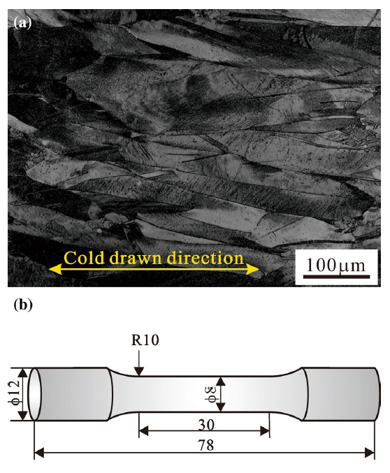
Commercially pure Cu was used in this investigation. Cylindrical specimens were machined from cold-drawn polycrystalline copper bars with its axial direction parallel to the drawing direction. The grains of cold-drawn copper are elongated along the cold-drawn direction. The average length and width of the grains are 554 μm and 41 μm, respectively, as shown in Fig. 1a. The tensile and torsional properties of cold-drawn copper are shown in Table 1. The related tension and torsion curves can be found in the article [21]. To guarantee the stabilization and larger surface shear stress of specimens subjected to torsion, the gauge size of the specimen is ϕ 8 mm × 30 mm. The shape and size of the fatigue specimens are illustrated in Fig. 1b. The torsional fatigue tests were conducted on an Instron 8874 multiaxial fatigue-testing machine under stress control, with a stress ratio of R=-1 at room temperature in air. The shear stress on the surface of the specimen was used in the plots. Based on Eq. (1) by Nadai [22], the surface shear stress, τr, can be calculated as below:
$\tau_{r} = \frac{1}{{2\pi r^{3} }}\left( {\theta \frac{dM}{d\theta } + 3M} \right),$ (1)
where r is the radius of cross section of the specimen gauge, θ is the rotation angle per unit length, M is the torque. The amplitudes of shear stress on the specimen surface selected are, respectively, 75 MPa, 90 MPa, 100 MPa and 150 MPa, which can make the fatigue life of cold-drawn copper within the concerned limits between 103 and 107. A sinusoidal waveform and a frequency of 15 Hz were used in the experiments. For these tests, the axial channel was in displacement control preventing the specimen to be changed in length and allowing the generation of axial stress. Before fatigue experiments, all the specimens were electrolytically polished to produce a strain-free surface for microscopic observations. After mechanical experiments, a LEO Supra 35 scanning electron microscope (SEM) was used to observe the fatigue cracking features on the specimen surfaces and the fracture surfaces. The microstructure of cold-drawn copper was observed by optical microscope (OM). The relationship between fatigue crack and the grain boundary were observed by SEM and OM.
Fig. 1 a Microstructure, b specimen geometry of cold-drawn copper used to fatigue test
Table 1 Tensile and torsional properties of cold-drawn copper
| Tension | Torsion | ||
|---|---|---|---|
| Yield stress, σs (MPa) | Uniform elongation, εu (%) | Strain to fracture, εf (%) | Yield stress, τs (MPa) |
| 260 ± 1 | 17.6 ± 1.93 | 41.7 ± 2.52 | 101 ± 1 |
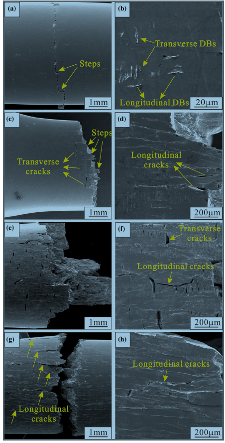
The typical surface morphological features near fracture surfaces of cold-drawn copper were examined after torsional fatigue, as displayed in Fig. 2. It can be seen that no matter whether in the microscopic or macroscopic scale, most of the fatigue cracks under torsional loading are oriented on the maximum shear plane (i.e., parallel or perpendicular to the axis of the specimen). This indicates that fatigue damage mechanism of cold-drawn copper is shear. This result is similar to those observed in torsional fatigue of pure titanium [7] and aluminum alloys [6, 8]. At the stress amplitude of 75 MPa, the largest part of the main crack is along the transverse direction, except that a very small portion is along the longitudinal direction, which leads to the appearance of small steps (Fig. 2a). Only a few short transverse and longitudinal deformation bands (DBs) appear (Fig. 2b). As we know, crack initiation under cyclic torsional loading normally happens at the specimen surface where highest shear stress is expected, so these DBs should be at the crack nucleation sites.
Fig. 2 Surface damage morphologies near the fracture surfaces of cold-drawn copper after torsional fatigue: a, b 75 MPa, c, d 90 MPa, e, f 100 MPa, g, h 150 MPa
At the stress amplitude of 90 MPa (Fig. 2c, d), more transverse and longitudinal DBs appear. Among them, the longitudinal DBs are longer than the transverse ones, while the transverse DBs are denser. Obvious transverse cracks can be seen near the fracture surface, and small longitudinal cracks begin to develop. Thus, the fracture of cold-drawn copper is mainly caused by the transverse crack under the applied stress amplitude. In addition, the number of the steps along the main crack is obviously more than that of 75 MPa, which make fracture surface more uneven.
When the stress amplitude is increased to 100 MPa (Fig. 2e, f), surface damage becomes more serious, both transverse and longitudinal cracks near the fracture surface increase in number and become more visible, resulting in a further increase in the degree of irregularity of fracture surface. Longitudinal cracks are much longer than transverse cracks.
At applied stress amplitude of 150 MPa (Fig. 2g, h), only long longitudinal cracks distinctly appear on one side of the fracture surface, and almost no transverse cracks grow on the specimen surface. That is why there is no surface step caused by both transverse and longitudinal shear. It is shown the fracture surface is rough and almost perpendicular to the axial direction of specimen.
It can be seen from the mentioned above, under all stress amplitudes, the crack growth behavior of cold-drawn copper belongs to the first type, that is, cracks extend only on the maximum shear planes, but not on the maximum normal stress planes. This is different from the observations in torsional fatigue of high strength steel and stainless steel [10, 11, 12].
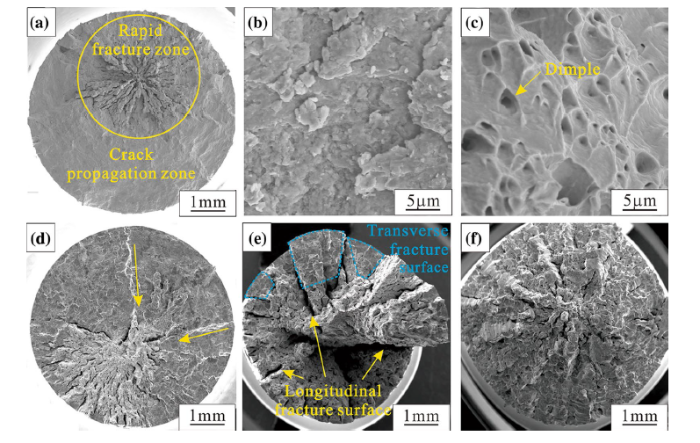
The fracture morphologies of cold-drawn copper are exhibited in Fig. 3. At the stress amplitude of 75 MPa, the fracture occurs along the transverse section (Fig. 3a). On a macroscale, the crack propagation zone is smooth, but its typical microscopic characteristic is noticeable abrasion marks, which is related to the wear of the two matching fracture surfaces during torsional fatigue (Fig. 3b). Macroscopically, rapid fracture zone is in the form of fibers that gather inward, and its microscopic feature is dimpled, which is the typical characteristic of static fracture of plastic material (Fig. 3c). This planar fracture morphology was first observed by Tschegg [23].
Fig. 3 Fracture morphologies of cold-drawn copper after torsional fatigue tests: a-c 75 MPa, d 90 MPa, e 100 MPa, f 150 MPa. b, c show the typical morphology of propagation zone and rapid fracture zone, respectively; the arrow in d denotes propagation direction of longitudinal cracks
When the stress amplitude is 90 MPa (Fig. 3d), the fracture feature is similar to that of 75 MPa. The difference is that traces of longitudinal crack propagation along the radial direction were found, which is consistent with the stepped main crack on the specimen surface in Fig. 2c and the longitudinal cracks in Fig. 2d.
For the applied stress amplitude of 100 MPa (Fig. 3e), the area of the transverse shear fracture surface makes up only a small proportion of the whole fracture surface. Multiple longitudinal cracks propagating along radial direction can be clearly seen, which bring about the appearance of the longitudinal shear fracture surface. A composite fracture surface manifests that not only includes transverse sections but also longitudinal sections. A large area of rapid fracture zone appears between the longitudinal shear fracture surfaces.
The fracture morphology of cold-drawn copper at the stress amplitude of 150 MPa is shown in Fig. 3f. It can be seen that the fracture surface is rough and presents a divergent shape, with no transverse shear fracture surface appearing. Combining the surface morphology exhibited in Fig. 2g, the fracture process of cold-drawn copper can be explained as follows. Multiple longitudinal cracks form first, but it is very difficult to break one specimen completely along its longitudinal direction. When these longitudinal cracks expand to a certain length and penetrate some distance internally, the adequate stress concentration of their tips will give rise to the growth of one circumferential crack. The propagation of this circumferential crack to the interior is actually a process of transversal fracture of parts between adjacent longitudinal shear fault surfaces, which can lead to the final disconnection of the cold-drawn copper specimen. Hence, based on this fracture process, the observed fracture surface is composed of all the rapid fracture zones between adjacent longitudinal shear fracture surfaces, and longitudinal shear fracture is the essential reason for the final fracture of cold-drawn copper under the stress amplitude of 150 MPa. Because longitudinal cracks could only grow along another direction after this circumferential principal crack forms, long longitudinal cracks simply appear on one side of the fracture surface (Fig. 2g).
Based on the above observations, the fatigue failure of cold-drawn copper is caused by the damage and fracture along the transverse or longitudinal direction. For the cold-drawn structure investigated here, because the longitudinal size of the grain is much larger than its transverse size and the grain boundaries are mainly distributed along longitudinal direction of the specimen (Fig. 1), it is necessary to study the relationship between the fatigue crack propagation path and the grain boundary. At the stress amplitude of 100 MPa, both the degrees of transverse and longitudinal shear are greater among all the amplitudes selected, so it is easy to study the relationship between torsional fatigue crack and grain boundary under this condition.
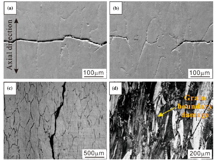
The relationship between torsional fatigue crack and the grain boundary of cold-drawn copper at the stress amplitude of 100 MPa is presented in Fig. 4. It can be seen that transverse cracks propagate across the interior of the grain (Fig. 4a, b), while longitudinal cracks grow along the grain boundaries (Fig. 4c). Figure 4d shows the microstructure on the longitudinal section of cold-drawn copper specimen after torsional fatigue under the stress amplitude of 100 MPa. It can be seen that compared with the initial structure of cold-drawn copper, a lot of fine broken crystals develop near the grain boundaries, which indicates that cyclic deformation causes serious damage at the grain boundaries. This damage could have an important effect on the relationship between fatigue crack and the grain boundary, which will be discussed in the following sections.
Fig. 4 Relationship between torsional fatigue crack and grain boundary of cold-drawn copper at the stress amplitude of 100 MPa: a, b transverse crack, c longitudinal crack, d microstructure on the longitudinal section of specimen
The fracture mode of cold-drawn copper is related to the cracking type on specimen surface. Based on the experimental results above, with the increase in stress amplitude, the cracking type transits from transverse shear to mixed shear on both transverse and longitudinal sections, then longitudinal shear, so do the changes in fracture modes. Although the drawn process could cause internal defects to be aligned with the drawn direction, which makes the longitudinal direction weaker than the transverse direction, the cracking type changes with stress amplitude increase. In view of the change of cracking type and fracture mode with stress amplitude and their close association, the study on the effect of stress amplitude on surface cracking type of cold-drawn copper specimens should be critical and make sense for analyzing the fracture mechanism of cold-drawn copper and will be discussed in depth in the following section.
According to the surface damage morphology of cold-drawn copper, there is a relatively concentrated area of fatigue damage in the middle of the specimen after cyclic deformation. When fatigue damage reaches a certain level, cracks appear first in this area. With the increase in stress amplitude, the width of the damage concentration zone increases continuously, as shown in Fig. 2. The fracture modes under different stress level may be related to the change of width of damage concentration zone with stress amplitude. Based on this idea, the fracture mechanisms of cold-drawn copper are analyzed.
When the stress amplitude is lower, surface damage of cold-drawn copper is relatively weaker (75 MPa), only some transverse and longitudinal DBs appear on specimen surface (Fig. 2b). In this case, the damage concentration area is very narrow. Thus, compared with longitudinal DBs, transverse DBs are more likely to lead to the formation of transverse main cracks and the fracture of the specimen. Therefore, the fracture mode of cold-drawn copper is shear on transverse section.
With the increase in stress amplitude, the damage concentration area becomes wider. In this circumstance, in addition to transverse cracks, there is more and more space for longitudinal cracks to grow. However, the tendency of crack propagation along transverse and longitudinal directions shows different trends with increasing amplitude: transverse cracking tendency decreases, while longitudinal cracking tendency increases. The different trends will have a close bearing on the change of the failure mode of cold-drawn copper. In the following section, the influence of stress amplitude on the propagation tendency of transverse and longitudinal cracks will be analyzed and explained from two aspects: (a) microstructure; (b) axial stress.
4.2.1 Microstructure
The relationship between fatigue crack and the grain boundary should be considered in order to analyze the tendency of fatigue crack propagation along transverse and longitudinal directions with the stress amplitude. It can be seen from the crack propagation path in Fig. 4 that the longitudinal crack propagates along the grain boundaries and the transverse crack grows through the grains. At the same time, severe fatigue damage was found at the grain boundaries. It is widely known that the grain boundary is one of the generation sites of fatigue cracks, which is related to the large degree of damage at the grain boundaries [24]. Cold-drawn structure here suffers severe grain boundary damage, which is manifested by the appearance of a large number of broken grains. The damage at the grain boundaries may also bring about the reduction in crack growth resistance, thus introducing the possibility that cracks can grow along grain boundaries more easily. On the other hand, due to the reduced surface distortion at the emergence of persistent slip bands (PSBs) and smaller compatibility stresses at the PSB-matrix interfaces, transgranular crack initiation and development could be delayed and intergranular crack initiation promoted under torsional loading [25]. Hence, under cyclic torsional loading, intergranular fatigue cracks propagate more easily compared with the transgranular crack. In addition, it is not difficult to observe that when the stress amplitude is 100 MPa, some cracks deviate from the transverse direction in the process of transverse crack propagation, and this deflection is exactly along the grain boundary (Fig. 4b). This phenomenon, in fact, to some extent also proves that torsional fatigue cracks tend to grow along the grain boundaries.
For the cold-drawn structure described here, because the grain boundaries are mainly along the longitudinal direction, the longitudinal crack propagates along the grain boundary and the transverse crack grows through the grain (Fig. 4a-c). More importantly, longitudinal grain boundaries are more continuous than transverse ones, macroscopic longitudinal cracks can form by interconnecting grain boundaries, while transverse cracks cannot. As a result, fatigue cracks tend to grow along longitudinal grain boundaries.
When the stress amplitude is lower, the damage concentration area is very narrow, so the fracture mode is transverse shear, and the crack cannot easily grow along the longitudinal direction. At higher stress amplitudes, the increased width of the damage concentration area can provide more and more space for fatigue crack propagation along the longitudinal direction. With the increase in stress amplitude, the damage at the grain boundary will be more and more serious, so fatigue cracks are likely to spread along the grain boundaries. Taking into account the width of damage concentration area and grain boundary damage, with increasing stress amplitude, the inclination of the crack propagating along the longitudinal grain boundaries increases and the probability of the transverse crack propagation becomes less and less.
4.2.2 Axial Stress
Figure 5 shows the relationship between axial stress and time when cold-drawn copper specimen was cycled to half of its total life at different stress amplitudes. It can be seen that the axial stress changes regularly with the period of 0.07 s, so the frequency of variation is the same as that of applied torsional stress, 15 Hz. Under different stress amplitudes, the variation law of axial stress is not identical. However, it contains both axial tension stress and compression stress at all applied shear stress amplitudes, and the amplitude of compression stress is always larger than that of tension stress. It is worth noting that the difference between compression stress amplitude and tension stress amplitude increases with the stress amplitude, that is to say, compared with axial tension stress, the axial compression stress will play a more prominent role in crack growth. In general, the axial tension stress will promote the growth of the transverse crack, while the axial compression stress will inhibit it. Consequently, the axial stress in cold-drawn copper should have an impediment effect on the propagation of the transverse crack, which will be enhanced with the increase in stress amplitude. This variation tendency of axial stress is consistent with the fact that cracks are more likely to propagate longitudinally at higher stress levels. Therefore, in a sense, the effect of axial stress on crack propagation tendency is similar to that of the microstructure of the cold-drawn copper specimen investigated here. However, as a matter of fact, it can be found that the axial stress in Fig. 5 is very small compared with the applied torsional shear stress. In fact, in the process of crack propagation, due to the stress concentration, the local stress at the crack tip should be greater than the measured axial stress, thus affecting the crack propagation. In addition, because axial stress acts in a different way compared with torsional shear stress, and it is also a cyclic stress, smaller axial stress may also play a certain role on the growth of fatigue cracks.
Fig. 5 Relationship between axial stress and time when cold-drawn copper specimen was cycled to half of its total life at different stress amplitudes: a 75 MPa, b 90 MPa, c 100 MPa, d 150 MPa
On the whole, both microstructure and axial stress increase the tendency of crack propagation along the longitudinal direction with the increase in stress amplitude. The common result of these two factors is that mixed shear fracture on both transverse and longitudinal sections happen in the medium stress amplitude.
In the case of higher stress amplitude (150 MPa), based on the above analysis, compared with transverse cracks, longitudinal crack propagation occurs so easily that there is no transverse crack growth (Fig. 2g). At this point, the longitudinal cracks become long and visible. When longitudinal cracks propagate to a certain extent, the complete disconnection of the specimens will occur suddenly. The final rupture of specimen is caused by the multiple fractures between adjacent longitudinal shear fracture surfaces, and the main crack surface is composed of all the rapid fracture zones between adjacent longitudinal shear fracture surfaces (Fig. 3f). Therefore, the fracture mode of cold-drawn copper is shear fracture on multiple longitudinal sections.
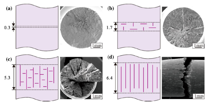
To conclude the above arguments, crack propagation and fracture morphology of cold-drawn copper under cyclic torsional loading are summarized in Fig. 6. The disparity in the crack propagation and failure type under different stress amplitudes can be well compared and analyzed. As presented in Fig. 6, with the cyclic torsional stress amplitude increase, the damage concentration area becomes wider, which provides the possibility for the propagation of longitudinal cracks. At the same time, due to the enlarged promotional effect of serious grain boundary damage on longitudinal crack propagation and the increased restraint effect of axial compression stress on transverse crack growth, the propensity of crack propagation along the longitudinal direction is increased, while that along the transverse direction is decreased. These result in different fracture modes of cold-drawn copper under different stress ranges: at lower stress amplitude, the fracture mode is transverse shear (Fig. 6a); then it is gradually transformed into a composite fracture with both transverse shear and longitudinal shear with increasing the stress amplitude (Fig. 6b, c); at higher stress amplitude, a complete longitudinal shear fracture takes place (Fig. 6d).
Fig. 6 Summary of crack propagation and fracture morphologies of cold-drawn copper under cyclic torsional loading: a 75 MPa, b 90 MPa, c 100 MPa, d 150 MPa. (The line segments with arrows denote the width of concentrated damage areas)
The investigation above is based on cold-drawn copper specimens with its drawing direction parallel to the longitudinal direction. The grain boundaries are mainly distributed along the longitudinal direction, which increases the fracture tendency on longitudinal sections. If one can avoid the longitudinal direction of shaft components parallel to the drawing direction, the longitudinal damage caused by the grain boundary distribution may decrease, and the fatigue performance of components should be improved. In a broader sense, the torsional fatigue properties of deformed materials can be optimized through reasonable orientation selection. Therefore, this work can provide a theoretical basis for the improvement of torsional fatigue performance of shaft components prepared from anisotropic materials. Further study will be performed to clarify this point.
1. With increasing stress amplitude, the fracture mode of cold-drawn copper gradually changes from a shear fracture on transverse section to a mixed shear fracture on both transverse and longitudinal sections, and finally turns to shear fracture on multiple longitudinal sections.
2. The change of fracture mode with the stress amplitude is related to the change of crack propagation direction.
3. With increasing stress amplitude, the grain boundary distribution of cold-drawn copper promotes crack propagation in a longitudinal direction.
4. With increasing stress amplitude, the axial stress caused by torsion inhibits the crack growth in a transverse direction.
5. Under the influence of grain boundary distribution and axial stress caused by torsion, the tendency of crack propagation along the longitudinal direction increases with increasing stress amplitude.
This work was supported by the National Natural Science Foundation of China (No. 51771208) and the Natural Science Foundation of Liaoning (No. 2019-ZD-0059).
The authors have declared that no competing interests exist.

 WeChat
/
| 〈 |
|
〉 |
