Search for articles:
Jin-Jin Zhao , Shuai Hu
Corresponding authors:
Received: 2019-03-7
Revised: 2019-04-24
Online: 2019-12-10
Copyright: 2019 Editorial board of Acta Metallurgica Sinica(English Letters) Copyright reserved, Editorial board of Acta Metallurgica Sinica(English Letters)
More
Abstract
An effect of Cl- concentration on the stress corrosion cracking (SCC) behavior of 13Cr stainless steel was investigated by employing electrochemical measurements and the slow strain rate tensile tests. These tests were conducted in various solutions with different concentrations of NaCl at 90 °C under 3 MPa CO2 with 3 MPa N2. The results indicate that the passive film of the specimen formed in the 10% NaCl solution has the best protective effect on the matrix. The SCC susceptibility does not increase with increasing the chloride ion concentration, the lowest SCC susceptibility occurs when the NaCl concentration is 10%, and the specimens show higher SCC susceptibility in the 5% NaCl and 20% NaCl solutions.
Keywords:
Stress corrosion cracking (SCC) has been recognized as a degradation issue in tubing and casing materials in recent years [1, 2, 3]. The tubing and casing materials contacting with aqueous solutions containing CO2 and Cl- undergo severe corrosion, such as localized corrosion and SCC [4, 5, 6, 7, 8]. Therefore, the materials used for pipelines are mainly selected based on their performance under increasingly severe environments [9, 10]. Martensitic stainless steels (MSS) with 13 wt% Cr have been widely used in oil and gas fields containing CO2 owing to their better corrosion resistance compared with conventional low-alloy steels and lower cost compared with other stainless steels, such as duplex stainless steel [11, 12, 13].
In recent years, the effects of Cl- or CO2 on the corrosion of tubing and casing materials have been widely investigated. On the one hand, it is clear that CO2 can react with water and cause CO2 corrosion. As reported, the CO2 corrosion rate decreases with increasing pH [14, 15, 16, 17] and solution salinity [18]. The chemical composition of CO2 corrosion product film can be changed with increasing temperature [19]. On the other hand, it is well known that Cl- can destroy the passive film on stainless steel and cause pitting corrosion. However, there is a lack of a consensus among researchers on the synergetic influences of Cl- and CO2 on corrosion behavior. Hausler [20] demonstrated that Cl- had no significant effect on CO2 corrosion, while Liu [18] found that increasing the concentration of Cl- could reduce CO2 solubility, and there existed a critical Cl- at which the CO2 corrosion rate of carbon steel reached a maximum value. When the concentration of Cl- is high, Cl- may exist in competitive relationship with CO2. Schmitt [21] showed that a high Cl- concentration could inhibit CO2 corrosion by decreasing the solubility of CO2 in solution at room temperature, agreeing with the opinion of Liu [18]. Furthermore, the co-effects of Cl- and CO2 on the corrosion of materials at high temperatures have not yet been clarified.
Several studies have investigated the SCC behavior of 13Cr stainless steel in dense phase CO2 with O2 [22] or neutral NaCl solutions [23]. Furthermore, it has been reported that the main corrosion feature of 13Cr stainless steel is localized corrosion at 60-120 °C which is the service temperature range of tubing pumps and severe pitting corrosion may occur at 90 °C [24]. However, when Cl- and CO2 coexist under the working conditions of tubing, SCC often occurs because of a combination of electrochemical and mechanical processes [25]. Thus far, a few researchers have studied the SCC behavior by using slow strain rate tensile (SSRT) tests and electrochemical techniques under high-temperature and high-pressure (HTHP) conditions with Cl- and CO2. Therefore, in this study, electrochemical measurements and SSRT tests were conducted to study the effect of Cl- on the SCC behavior of 13Cr stainless steel under the temperature of 90 °C with 3 MPa CO2 and 3 MPa N2.
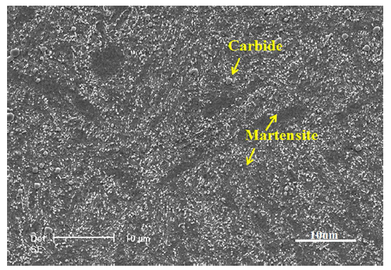
The experimental material was 13Cr stainless steel with the chemical composition listed in Table 1. 13Cr stainless steel was a typical tempered martensitic microstructure with a small amount of the carbides, as shown in Fig. 1. An electrochemical specimen with a dimension of 20 mm × 20 mm × 3 mm was used in this study. The entire surface of the electrochemical specimen was polished up to 800 grit; then, the specimen was washed with distilled water and alcohol and then allowed to dry in ambient air. The SSRT specimen was a φ5 rod sample. Its test section was polished sequentially to 1000 grit with emery paper, ultrasonically washed using alcohol, and dried at room temperature.
Table 1 Chemical composition of 13Cr stainless steel
| Element | C | Cr | Mn | Si | Cu | Ni | S | P | Fe |
|---|---|---|---|---|---|---|---|---|---|
| Wt% | 0.2 | 13.05 | 0.54 | 0.54 | 0.06 | 0.13 | 0.007 | 0.015 | Bal. |
Fig. 1 The microstructure of 13Cr stainless steel samples
The electrochemical specimen was immersed in an autoclave for 24 h at a temperature of 90 °C with 3 MPa CO2 and 3 MPa N2 (gas-phase pressure). The deoxidized solutions in the autoclave were NaCl solutions with the concentrations of 5, 10, and 20% (wt). After the immersion, the specimen was conducted by using the PARSTAT 2273. The traditional three-electrode system used is composed of the specimen, platinum, and the Ag/AgCl acting as the working electrode, counter electrode, and reference electrode, respectively. Polarization measurement regions were set from 100 mV below the open-circuit potential and began from the cathodic side at a constant scanning rate of 0.333 mV/s after an initial delay of 600 s. The Mott-Schottky measurement was taken using a potential scan toward the anodic direction with a scanning rate of 20 mV/s. An AC signal with an amplitude of 10 mV and a frequency of 6000 Hz was superimposed on the scanning signal.
In this study, the tensile tests of 13Cr stainless steel specimen were performed by a TOSHIN SSRT machine. The SCC behaviors of 13Cr were investigated in 0% (by weight, the same below), 5, 10, and 20% NaCl solutions in the autoclave. For tests in the autoclave, the solutions were heated to 90 °C and bubbled by N2 for 1 h to remove oxygen. Then, CO2 and N2 were pressurized to 3 MPa and 6 MPa, respectively, and the pressure was monitored by a manometer on the autoclave. Finally, the tensile specimen was stretched at an extension rate of 8 × 10⁻⁷ s-1 after a 24-h immersion in the chloride solution.
The micromorphology and fractography were observed using a Philips XL30 scanning electron microscopy (SEM) equipped with an energy-dispersive X-ray spectroscopy (EDX). The corroded samples were sputtered with carbon or gold for better morphology observation.
3.1.1 Polarization Curves
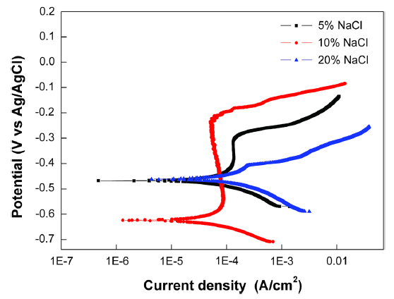
Figure 2 shows the polarization curves of 13Cr stainless steel specimens immersed in NaCl solutions, with different concentrations (5%, 10%, 20% NaCl) for 24 h. It can be seen that the polarization curves measured under the three conditions exhibit different features. The 13Cr stainless steel specimens in the 5% and 10% NaCl solutions show obvious passive characteristics; by contrast, the curve for the specimen that was immersed in the 20% NaCl solution shows active dissolution characteristics. It can be seen that, compared with the specimen in the 5% NaCl condition, the specimen in the 10% NaCl condition exhibited decreased passive current density (Ipass), and that in the 20% solution exhibited increased corrosion current density (Icorr). For 13Cr stainless steel, the increase in Icorr accelerates anodic iron dissolution. The curve of the 13Cr stainless steel specimen in the 10% NaCl solution exhibits a passivation region with obvious higher pitting corrosion potential (Epit) than that of the specimen in the 5% NaCl solution, which indicates specimen in the 10% NaCl solution has a better ability to resist pitting corrosion.
Fig. 2 Polarization curves of 13Cr stainless steel in NaCl solution with various chlorine concentrations
Table 2 shows the electrochemical parameters of the polarization curves of the 13Cr specimens in NaCl solution, where Ecorr is the corrosion potential in mV vs. Ag/AgCl and Icorr is the corrosion current density in uA cm-2. As given in Table 2, the current density Icorr decreases first and then increases with increasing chloride concentration. The specimen in the 10% NaCl solution has the lowest value of 42.58 uA cm-2, which indicates the passive film offers the best protection against the matrix. However, the value of Icorr reaches 117.4 uA cm-2 for the specimen in the 20% NaCl solution, indicating that the protective benefits of the matrix have weakened.
Table 2 Electrochemical parameters of the polarization curves for 13Cr stainless steel immersed in various NaCl solutions
| NaCl (%) | T (°C) | P (MPa) | Ecorr (mV) | Icorr (uA cm-2) |
|---|---|---|---|---|
| 5 | 90 | 6 | - 467.58 | 69.47 |
| 10 | 90 | 6 | - 609.47 | 42.58 |
| 20 | 90 | 6 | - 452.137 | 117.40 |
3.1.2 Mott-Schottky Curves
The effect of Cl- concentration on the semiconducting properties of the passive film was investigated by capacitance measurements. The relationship between capacitance and the applied potential is given by the Mott-Schottky equation as follows [26]:
$ {\text{C}}^{ - 2} = \frac{2}{{\varepsilon \varepsilon_{0} eN_{\text{D}} }}\left[ {E - E_{\text{FB}} - \frac{KT}{e}} \right]\quad n{\text{-type}}, $ (1)
$ {\text{C}}^{ - 2} = \frac{2}{{\varepsilon \varepsilon_{0} eN_{\text{A}} }}\left[ {E - E_{\text{FB}} - \frac{KT}{e}} \right] \quad p{\text{-type}}, $ (2)
where ε0 is the permittivity in vacuum (8.85 × 10⁻¹⁴ F cm-1), ε the dielectric constant of the passive film, usually taken as 15.6 [27], e the electron charge (1.602 × 10⁻¹⁹ C), ND the donor density for an n-type semiconductor, NA the acceptor density for a p-type semiconductor, Efb the flat band potential, k the Boltzmann constant, and T the absolute temperature.
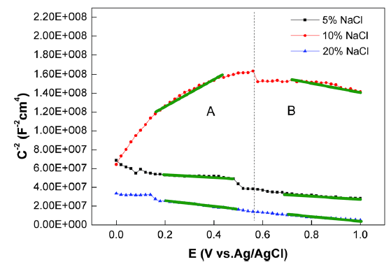
Figure 3 displays the Mott-Schottky plots for the passive films formed on the 13Cr stainless steel specimens after the specimens were immersed for 24 h in NaCl solutions with concentrations of 5, 10, and 20%. As shown in Fig. 3, the Mott-Schottky plots can be divided into two regions by the slope, and a linear relationship can be observed between C-2 and E in all solutions in the A (0.2-0.5 V) and B (0.7-1.0 V) regions, respectively.
Fig. 3 Mott-Schottky curves of 13Cr stainless steel in NaCl solution with various chlorine contents
In region A, the slopes of the specimens in the 5% and 20% NaCl solutions are negative, indicating that cation vacancies are the main defect in the passive film that behaves as p-type semiconductors; however, the slope of the specimen in 10% NaCl is positive, which demonstrates that oxygen vacancies are the dominate defect in the passive film such that the passive film behaves as an n-type semiconductor. In region B, the slopes of the specimens in the three solutions are negative, indicating that the specimens act like p-type semiconductors. According to the PDM model [28], an oxygen vacancy can adsorb Cl- and react with it through a Mott-Schottky pair to produce oxygen vacancy/metal ion vacancy pairs, which can prevent the growth of the passive film and destroy it eventually. Therefore, the more the oxygen vacancies and metal ion vacancies that are contained in the passive film, that is, the higher ND or NA in the passive film, the more the vulnerable passive film to be destroyed.
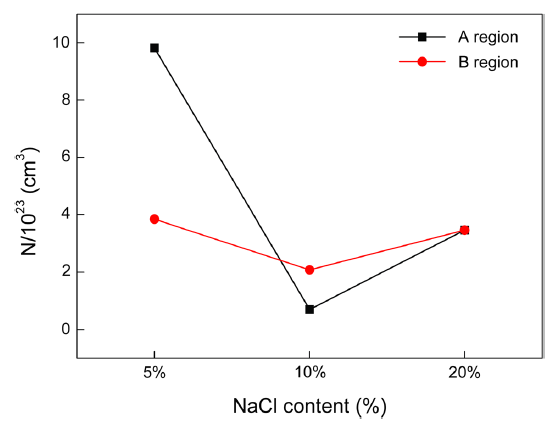
The values of ND and NA can be calculated by the slope according to Eqs. (1) and (2). Figure 4 shows the calculated donor and acceptor densities of the films formed on the specimens in the three solutions. For all the three solutions, the donor or acceptor density decreases first and then increases with the increases in Cl- concentration in regions A and B. The order of the donor or acceptor density is 5% > 20% > 10%. As reported [26, 29], the passive film can easily rupture and undergo pitting corrosion with the increases in donor or acceptor density. Therefore, the passive film of the specimen in the 10% NaCl solution is more stable than those in the 5% and 20% NaCl solutions; moreover, the film easily undergoes pitting corrosion in the 5% NaCl solution and easily ruptures in the 20% NaCl solution. The results are consistent with the polarization curves.
Fig. 4 The NA or ND of specimens in NaCl solution with various chloride ion concentrations after immersing 24 h at the OCP
3.2.1 Stress-Strain Curves
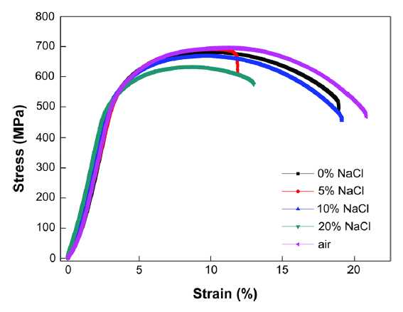
The stress-strain curves of 13Cr stainless steel in solutions with different NaCl concentrations are shown in Fig. 5. To investigate the effect of Cl- concentration on the cracking behavior of the 13Cr stainless steel in a 3 MPa CO2 and 3 MPa N2 environment, SSRT tests were also conducted in the test solution without the addition of chlorine ions, i.e., in a 0% NaCl solution. It can be seen that the five specimens exhibit different stress-strain behaviors. The highest elongation loss occurs in the 5% NaCl solution condition at 90 °C.
Fig. 5 Stress-strain curves of 13Cr stainless steel in the different NaCl solutions at 90 °C
Furthermore, Fig. 5 shows that the addition of Cl- apparently increases the elongation loss of the specimens. Meanwhile, the elongation loss decreases first and then increases with an increase in Cl- concentration. The highest specimen elongation loss occurs in the 5% NaCl solution. A further observation of the curves indicates that the corresponding order of the elongation loss in NaCl solution is 5% > 20% > 10% > 0%.
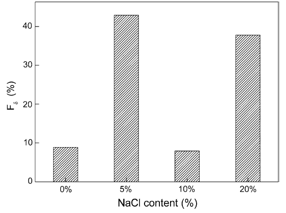
In the present work, the SCC susceptibility can be represented by elongation loss rate (Fδ) [30], as shown in Fig. 6. The definition of the rate is as follows:
$ F_{\delta } = \, \left( {\delta_{0} {-} \, \delta } \right)/\delta_{0} \times \, 100\% , $ (3)
where δ is the elongation of 13Cr stainless steel in various Cl- concentrations under 3 MPa CO2 and 3 MPa N2 conditions at 90 °C and δ0 is the elongation of 13Cr stainless steel measured in air at 90 °C.
Fig. 6 NaCl content dependence of the SCC susceptibilities with elongation loss rate
As Fδ is the ductility loss parameter, it is apparent that the addition of chlorine increases the SCC susceptibilities of 13Cr stainless steel. Generally, increasing the Cl- concentration enhances the diffusion of Cl-. It is reasonable to deduce that more Cl- will penetrate the steel, which will contribute to the SCC process. Figure 6 shows that the SCC susceptibilities of the steel depend on the Cl- concentration and, thus, also depend on the CO2 partial pressure and solubility. The susceptibility indices Fδ of the specimens are as high as 42.89% in the 5% NaCl solution and 37.78% in the 20% NaCl solution, which demonstrate the specimens undergo SCC. However, Fδ is only 7.94% in the 10% NaCl solution, indicating that the specimen does not undergo SCC.
3.2.2 Fractography After the SSRT Tests
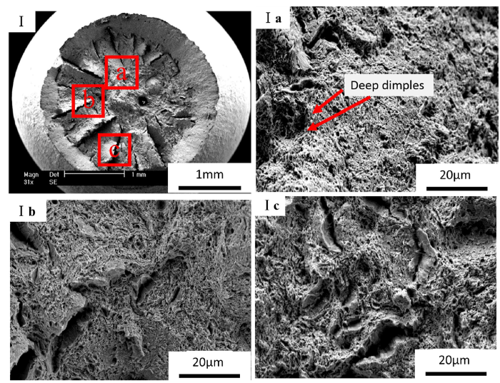
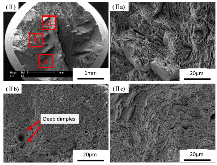
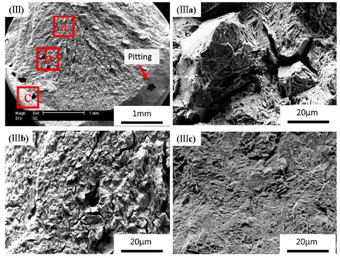
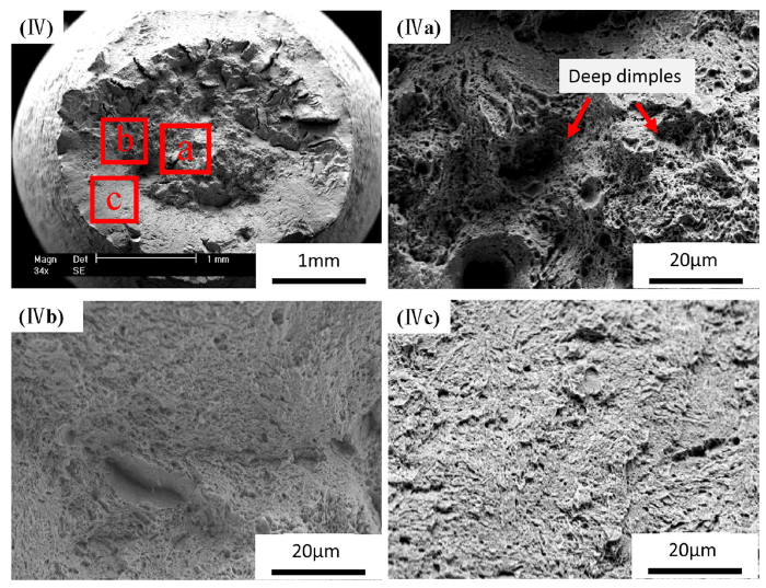
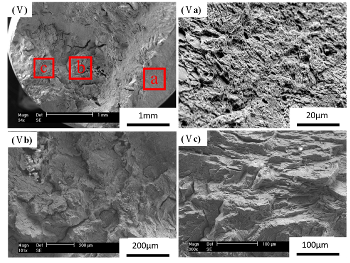
The fractography of the 13Cr stainless steel specimens in NaCl solutions with different concentrations at 90 °C was examined using SEM. The results are shown in Figs. 7, 8, 9, 10, and 11. Figures 7 and 8 show the main ductile fracture morphology in air and the 0% NaCl solution, respectively, which display significant necking and typical cup-and-cone fracture surface. Furthermore, deep dimples morphologies are exhibited on the fracture (Fig. 7(Ia), Fig. 8(IIb)). From the above results, it can be concluded that the 13Cr stainless steel has good toughness and does not show SCC characteristics. The fracture surface is brittle with some pits on the edge when the NaCl concentration is 5%, as shown in Fig. 9(III). Figure 9(IIIb) shows that the intergranular fracture and corrosion products observed on the fracture surface are compact and crystal-like. However, the obvious fiber zone, radiation zone, and shear lip are exhibited by the specimen immersed in the 10% NaCl solution, as shown in Fig. 10(IV). Furthermore, the center of the fracture surface is full of dimples, as shown in Fig. 10(IVa). The dimple is a distinguishing feature of a ductile fracture. It has a relationship with the passive film of the specimen that exhibits on the polarization curve in the 10% NaCl condition. The Cl- and CO32- are in a competitive relationship that does not damage the corrosion film of 13Cr steel; thus, the stress concentration phenomenon cannot occur, and the specimen does not undergo SCC, eventually experiencing a ductile fracture. As shown in Fig. 11(V) and (Vb), the fracture surface of 13Cr steel in the 20% NaCl solution exhibits brittle features with a number of cracks. Under the tensile stress condition, a high concentration of Cl- reduces the protective effects of the film, so the Cl- can enter the matrix more easily and produce micro-cracks. When the number of cracks reaches a certain number, the specimen will break [23, 31]. Therefore, the specimens in the 5% and 20% NaCl solutions exhibit brittle cracks. This result agrees with the aforementioned evaluation results of SCC susceptibility parameters obtained at various NaCl concentrations.
Fig. 7 Microscopic morphologies of SSRT fracture of 13Cr steel in inert environment in air at 90 °C
Fig. 8 Microscopic morphologies of SSRT fracture of 13Cr steel in inert environment in the 0% NaCl solution at 90 °C with 3 MPa CO2 partial pressure
Fig. 9 Microscopic morphologies of SSRT fracture of 13Cr steel in inert environment in the 5% NaCl solution at 90 °C with 3 MPa CO2 partial pressure
Fig. 10 Microscopic morphologies of SSRT fracture of 13Cr steel in inert environment in the 10% NaCl solution at 90 °C with 3 MPa CO2 partial pressure
Fig. 11 Microscopic morphologies of SSRT fracture of 13Cr steel in inert environment in the 20% NaCl solution at 90 °C with 3 MPa CO2 partial pressure
Henry’s law constant for CO2 decreases with an increase in salinity [32, 33]. Generally, the salinity of a solution increases with Cl- concentration. Hence, increasing the Cl- concentration can obviously reduce CO2 solubility in water at a constant temperature and CO2 gas partial pressure. Once dissolved in water, CO2 forms carbonic acid (H2CO3), which is unstable and can be ionized into H+, HCO3-, and CO32-. The equilibrium reactions that proceed during the CO2 dissolution process and the corresponding reaction equilibrium constants are listed as follows [34, 35, 36]:
$ {\text{CO}}_{{ 2 ( {\text{g)}}}} \to {\text{CO}}_{{ 2 ( {\text{aq)}}}} \quad K_{\text{H}} = \frac{{a_{{{\text{CO}}_{ 2} }} }}{{f_{{{\text{CO}}_{ 2} }} }} = \frac{{C_{{{\text{CO}}_{ 2} }} }}{{\varphi P_{{{\text{CO}}_{ 2} }} }}, $ (4)
$ {\text{CO}}_{{ 2 ( {\text{aq)}}}} + {\text{ H}}_{2} {\text{O}} \to {\text{H}}_{2} {\text{CO}}_{3} \quad K_{\text{Hy}} = \frac{{a_{{{\text{H}}_{ 2} {\text{CO}}_{ 3} }} }}{{a_{{{\text{CO}}_{ 2} }} }} = \frac{{C_{{{\text{H}}_{ 2} {\text{CO}}_{ 3} }} }}{{C_{{{\text{CO}}_{ 2} }} }}, $ (5)
$ {\text{H}}_{2} {\text{CO}}_{3} \to {\text{H}}^{ + } + {\text{HCO}}_{3}^{ - } \quad K_{1} = \frac{{a_{{{\text{HCO}}_{ 3}^{ - } }} \cdot a_{{{\text{H}}^{ + } }} }}{{a_{{{\text{H}}_{ 2} {\text{CO}}_{ 3} }} }} = \frac{{\gamma_{ \pm 2}^{2} \cdot C_{{{\text{HCO}}_{ 3}^{ - } }} \cdot C_{{{\text{H}}^{ + } }} }}{{C_{{{\text{H}}_{ 2} {\text{CO}}_{ 3} }} }}, $ (6)
$ {\text{HCO}}_{3}^{ - } \to {\text{H}}^{ + } + {\text{CO}}_{3}^{2 - } \quad K_{2} = \frac{{a_{{{\text{CO}}_{ 3}^{{ 2 { - }}} }} \cdot a_{{{\text{H}}^{ + } }} }}{{a_{{{\text{HCO}}_{ 3}^{ - } }} }} = \frac{{\gamma_{ \pm 3} \cdot C_{{{\text{CO}}_{ 3}^{{ 2 { - }}} }} \cdot C_{{{\text{H}}^{ + } }} }}{{C_{{{\text{HCO}}_{ 3}^{ - } }} }}, $ (7)
$ {\text{H}}_{2} {\text{O}} \to {\text{H}}^{ + } + {\text{OH }}^{ - } \quad K_{W} = a_{{{\text{H}}^{ + } }} \cdot a_{{{\text{OH}}^{ - } }} = \gamma_{ \pm 4}^{2} \cdot C_{{{\text{H}}^{ + } }} \cdot C_{{{\text{OH}}^{ - } }} , $ (8)
where KH, KHy, K1, K2, and KW are the equilibrium constants of Reactions (4)-(8), respectively, I is the ionic strength, and φ is the fugacity coefficient. The mean ionic activity coefficients $ \gamma_{ \pm 2} $, $ \gamma_{ \pm 3} $, and $ \gamma_{ \pm 4} $ in the solution are about 0.662 [37]. The constant in equilibrium is a function of temperature and can be easily determined by the information in the open literature [34].
I and φ can be expressed as follows:
$ I = \frac{1}{2} \sum m_{\text{i}} z_{\text{i}}^{2} , $ (9)
$ { \log }\varphi = p\left( {0.0031 - \frac{1.4}{{T_{\text{K}} }}} \right), $ (10)
where mi is the molar concentration of the ion in the solution, Zi is the charge, P is the pressure (bar), and Tk is the temperature in Kelvin degree.
When the temperature and pressure are fixed, these reaction equilibrium constants can be determined using the formulas listed in Table 3.
Table 3 Experimental formulas for the calculation of the equilibrium constant
| Constant |
|---|
| $ {\mathbf{K}}_{{\mathbf{H}}} = \frac{{{\mathbf{C}}_{{{\mathbf{CO}}_{2} }} }}{{{\mathbf{\varphi }} \cdot {\mathbf{P}}_{{{\mathbf{CO}}_{2} }} }} = \frac{14.5}{1.00258} \times 10^{{ - \left( {2.27 + 5.65 \times 10^{ - 3} {\mathbf{T}}_{{\mathbf{f}}} - 8.06 \times 10^{ - 6} {\mathbf{T}}_{{\mathbf{f}}}^{2} + 0.075 \times {\mathbf{I}}} \right)}} \left( {{\mathbf{molar}}/{\mathbf{bar}}} \right) $ |
| $ {\mathbf{K}}_{{{\mathbf{Hy}}}} = \frac{{{\mathbf{C}}_{{{\mathbf{H}}_{2} {\mathbf{CO}}_{3} }} }}{{{\mathbf{C}}_{{{\mathbf{CO}}_{2} }} }} = 2.58 \times 10^{ - 3} $ |
| $ {\mathbf{K}}_{1} = \frac{{\gamma_{ \pm 1}^{2} {\mathbf{C}}_{{{\mathbf{HCO}}_{3}^{ - } }} {\mathbf{C}}_{{{\mathbf{H}}^{ + } }} }}{{{\mathbf{C}}_{{{\mathbf{H}}_{2} {\mathbf{CO}}_{3} }} }} = 387.6 \times 10^{{ - \left( {6.41 - 1.594 \times 10^{ - 3} {\mathbf{T}}_{{\mathbf{f}}} + 8.52 \times 10^{ - 6} {\mathbf{T}}_{{\mathbf{f}}}^{2} - 3.07 \times 10^{ - 5} {\mathbf{p}} - 0.4772 \times {\mathbf{I}}^{{1/2}} + 0.1180 \times {\mathbf{I}}} \right)}} \left( {{\mathbf{molar}}} \right) $ |
| $ {\mathbf{K}}_{2} = \frac{{{\mathbf{C}}_{{{\mathbf{H}}^{ + } }} {\mathbf{C}}_{{{\mathbf{CO}}_{3}^{2 - } }} }}{{{\mathbf{C}}_{{{\mathbf{HCO}}_{3}^{ - } }} }} = 10^{{ - \left( {10.61 - 4.97 \times 10^{ - 3} {\mathbf{T}}_{{\mathbf{f}}} + 1.331 \times 10^{ - 5} {\mathbf{T}}_{{\mathbf{f}}}^{2} - 2.624 \times 10^{ - 5} {\mathbf{p}} - 1.86 \times {\mathbf{I}}^{{1/2}} + 0.3466 \times {\mathbf{I}}} \right)}} \left( {{\mathbf{molar}}} \right) $ |
| $ {\mathbf{K}}_{{\mathbf{W}}} = {\mathbf{C}}_{{{\mathbf{H}}^{ + } }} {\mathbf{C}}_{{{\mathbf{OH}}^{ - } }} = 10^{{ - \left( {29.3868 - 0.0737549{\mathbf{T}}_{{\mathbf{k}}} + 7.47881 \times 10^{ - 5} {\mathbf{T}}_{{\mathbf{k}}}^{2} } \right)}} \left( {{\mathbf{molar}}^{2} } \right) $ |
In the CO2/H2O/NaCl system, according to the electro-neutrality theory, the positive charge and the negative charge have the following relationship:
$ {\text{C}}_{{{\text{Na}}^{ + } }} + {\text{C}}_{{{\text{H}}^{ + } }} = {\text{C}}_{{{\text{Cl}}^{ - } }} + {\text{C}}_{{{\text{OH}}^{ - } }} + {\text{C}}_{{{\text{HCO}}_{ 3}^{ - } }} + 2{\text{C}}_{{{\text{CO}}_{ 3}^{{ 2 { - }}} }} , $ (11)
where $ C_{{{\text{Na}}^{ + } }} $ and $ C_{{{\text{Cl}}^{ - } }} $ are the concentrations of Na+ and Cl- in the solution (mol/L), respectively, and they are equal. By combining the equilibrium constant formulas with Reactions (4)-(8), a mathematical equation in terms of $ C_{{{\text{H}}^{ + } }} $ can be obtained:
$ {\text{C}}^{3}_{{\left( {{\text{H}}^{ + } } \right)}} - \frac{{K_{W} + K_{1} \cdot K_{\text{Hy}} \cdot C_{{{\text{CO}}_{ 2} }} }}{{\gamma^{2} }}C_{{{\text{H}}^{ + } }} - \frac{{2K_{2} K_{1} \cdot K_{\text{Hy}} C_{{{\text{CO}}_{ 2} }} }}{{\gamma^{3} }} = 0. $ (12)
Microsoft Excel was used to calculate the concentrations of the various species in different NaCl solutions at 90 °C by solving Eq. (12). The calculated values are listed in Table 4. The results reveal that a decrease in CO2 solubility can reduce the concentrations of H+, HCO3-, and H2CO3; therefore, the $ {\text{C}}_{{{\text{H}}^{ + } }} $ of the 5% NaCl solution is higher than that of the 20% NaCl solution, as given in Table 4. The result is in agreement with the finding of Liu [18] and Schmitt [21] that CO2 solubility decreases with an increase in the concentration of Cl.
Table 4 Ion concentrations (M) in the NaCl solution with various chlorine contents in the environment of 90 °C and 3 MPa CO2 partial pressure
| NaCl (wt%) | $ {\mathbf{C}}_{{{\mathbf{CO}}_{2} }} $ | $ {\mathbf{C}}_{{{\mathbf{H}}_{2} {\mathbf{CO}}_{3} }} $ | $ {\mathbf{C}}_{{{\mathbf{HCO}}_{3}^{ - } }} $ | $ {\mathbf{C}}_{{{\mathbf{CO}}_{3}^{2 - } }} $ | $ {\mathbf{C}}_{{{\mathbf{H}}^{ + } }} $ |
|---|---|---|---|---|---|
| 5 | 0.2906 | 7.4977E-4 | 7.5626E-4 | 6.80145E-10 | 7.5626E-4 |
| 10 | 0.2466 | 6.3633E-4 | 7.6903E-4 | 9.70197E-10 | 7.6903E-4 |
| 20 | 0.1716 | 4.4277E-4 | 6.7202E-4 | 9.85576E-10 | 6.7202E-4 |
The stress-strain curves of 13Cr stainless steel indicate the specimens in the 5% NaCl and in the 20% NaCl solutions show higher SCC susceptibility, while the specimen in the 10% NaCl solution exhibits a lower SCC susceptibility and does not undergo SCC. It has a relationship with the passive film of the specimen that exhibits on the polarization curve and Mott-Schottky curve in the 10% NaCl condition, as shown in Figs. 2 and 3. Though the higher $ {\text{C}}_{{{\text{H}}^{ + } }} $ and the more chlorine concentration than in the 5% NaCl solution, the passive film in the 10% NaCl solution is more stable and has higher ability to resist pitting corrosion. If we assume that the Cl- and CO32- are in a competitive relationship that does not damage the corrosion film of 13Cr steel, the stress concentration phenomenon cannot occur, and the specimen does not undergo SCC. For the specimens in the 5% and 20% NaCl solutions under a 3 MPa CO2 partial pressure condition, according to the result in Table 4, the number of H+ is higher in the 5% NaCl solution than in the 20% NaCl solution, but the Cl- concentration is lower in the 5% NaCl solution than in the 20% NaCl condition; therefore, the SCC mechanisms are probably different.
Generally, for the specimen in the 5% NaCl solution under the 3 MPa CO2 condition, the anodic reaction in the CO2 corrosion process is the dissolution of Fe, and the cathodic reactions consist of the reduction of H+, HCO3-, and CO32-. The cathodic reactions are presented as follows [38]:
$ {\text{H}}_{2} {\text{CO}}_{3} + {\text{e}} \to {\text{HCO}}_{3}^{ - } + {\text{H,}} $ (13)
$ {\text{HCO}}_{3}^{ - } + {\text{e}} \to {\text{CO}}_{3}^{2 - } + {\text{H,}} $ (14)
$ {\text{H}}^{ + } + {\text{e}} \to {\text{H}} . $ (15)
Equations (13)-(15) describe the equilibrium reactions that proceed during the CO2 dissolution process. Apparently, dissociation of H2CO3 serves as an additional source of H, contributing to an enhanced cathodic reaction [39]. The hydrogen atoms then enter the metal matrix, leading to an increase in hydrogen permeation current. The enrichment of hydrogen in the metal matrix accelerates SCC of 13Cr steel. Moreover, H+ can form a local positive charge zone that attracts Cl- to the defect in the film. When the Cl- concentration reaches a critical value, pitting is induced [40], as shown in Fig. 3, where it can be observed that the specimen more easily undergoes pitting corrosion in the 5% NaCl solution. Meanwhile, hydrogen atoms enter the metal matrix easily depending on the pitting zone, thus increasing the hydrogen concentration in the local zone. Eventually, the specimen undergoes a stress concentration phenomenon in the pitting zone with a high hydrogen content under the condition of tensile stress, which leads to an intergranular fracture, as shown in Fig. 9(III). Consequently, the specimen shows the highest susceptibility to SCC in the 5% NaCl with 3 MPa CO2 condition; furthermore, SCC is accompanied by some pits on the edge, and the brittle fracture is of the intergranular type. According to the above analysis, the SCC behavior of the specimen in the 5% NaCl is supposed to be controlled by hydrogen-induced cracking.
However, the $ {\text{C}}_{{{\text{H}}^{ + } }} $ decreases and the Cl- concentration increases in the 20% NaCl solution. Accordingly, the high Cl- concentration can significantly reduce CO2 solubility [21, 41] and decrease the opportunities of H+, HCO3-, and H2CO3 to participate in the reaction [20]. Therefore, on the one hand, an increase in Cl- concentration can promote the anodic reaction, but on the other hand, the cathodic reaction is inhibited by the increasing Cl- concentration. In the environment of 20% NaCl and 3 MPa CO2 partial pressure with tensile stress, the adsorption of active Cl- at the initial stage followed by Cl- deposition on the film surface results in the 13Cr steel being readily susceptible to SCC in the solution containing Cl-. Under stress conditions, the dislocations begin to slip until the film on the surface breaks down and glide step appears. At this stage, the metal is exposed. The metal is the anode, and the passive film is the cathode, which leads to partial dissolution. The gap surface that is dissolved can form a new passive film. As shown in Fig. 2, the passive film of the specimen in the 20% NaCl solution is unstable and can be easily ruptured. Therefore, the rate of dissolution of the passive film is faster than the rate of re-passivation under the tensile stress condition, and the stress crack is initiated when the process of dissolution-re-passivation is repeated. Consequently, as shown in Fig. 11(V), the fracture has an abundance of continuous cracks. The above analysis reveals that the SCC behavior of the specimen in the 20% NaCl is supposed to be controlled by the anodic dissolution process.
The primary aim of this study was to examine the effect of Cl- concentration on the SCC susceptibility of 13Cr steel under temperature and partial pressure conditions of 90 °C and 3 MPa CO2, respectively, and to explore the mechanism of stress corrosion cracking. The main conclusions are listed as follows:
(1) Cl- can influence the SCC of 13Cr stainless steel and increase the risk of material failure. The SCC susceptibility decreases first and then increases with the increase in Cl- concentration. The highest susceptibility occurs in the 5% NaCl solution. The order of the susceptibilities is 5% > 20% > 10%.
(2) The 13Cr stainless steel specimen in the 10% NaCl solution shows more obvious passive characteristics and a higher Epit than the specimen in the 5% NaCl solution; the passive film offers the best protection against the matrix than those of the specimens in the 5% and 20% NaCl solutions.
(3) The SCC behavior of the 13Cr stainless steel specimen in the 5% NaCl solution is supposed to be controlled by hydrogen-induced cracking and that of the specimen in the 20% NaCl solution is supposed to be controlled by anodic dissolution. The specimen in the 10% NaCl solution does not exhibit SCC behavior.
This study was supported by National Natural Science Foundation of China (Grant Number: 51501199). The authors acknowledge the assistance.
The authors have declared that no competing interests exist.

 WeChat
/
| 〈 |
|
〉 |