Search for articles:
Xiang Qiu , Tian-Ying Xiong
Corresponding authors:
Received: 2019-02-21
Revised: 2019-04-11
Online: 2019-12-10
Copyright: 2019 Editorial board of Acta Metallurgica Sinica(English Letters) Copyright reserved, Editorial board of Acta Metallurgica Sinica(English Letters)
More
Abstract
In this study, alumina/A380 composite coatings were fabricated by cold spray. The influence of alumina particulates’ morphology (spherical and irregular) and content on the deposition behavior of the coatings (including surface roughness, surface residual stress, cross-sectional microstructure and microhardness) was investigated. Results revealed that the spherical alumina mainly shows micro-tamping effect during deposition, which result in remarkable low surface roughness and porosity of the coatings. In addition, very low deposition efficiency and good interfacial bonding between the coating and the substrate were achieved. For irregular alumina particles, the embedding of ceramic particulates in the coating was dominant during deposition process, resulting in high retention in the final deposit. However, it showed limited influence on porosity, surface roughness and interfacial bonding of the deposit. The coatings containing irregular alumina particulates exhibited much higher microhardness than those containing spherical alumina due to the higher load-bearing capacity of deposited alumina.
Keywords:
Cold spray is a relatively new solid-state material fabrication technique that relies on gas dynamic principle. In this process, feedstock powders (mainly 10-50 μm in size) are injected to a de Laval-type nozzle to form a high-velocity jet [1, 2] and powerfully impact onto the surface of a substrate to form the coating. During the entire cold-spray process, the temperature of feedstock powders is remained to be below the melting point [3, 4]. Therefore, oxidation, phase transformation and undesired chemical reactions in the final coatings can be effectively avoided when compared with traditional high-temperature spraying processes [5, 6, 7, 8]. This makes cold spray as an emerging technique to form coating, additive manufacturing or repairing variety of engineering materials [5, 9]. According to the literature, it is technically possible to deposit almost all the metallic materials with any thickness (above 50 μm) by cold-spray process [5].
However, as an emerging technique, the cold spray has certain limitations in additive manufacturing of engineering materials, especially when medium-/low-pressure cold spray systems are used. The dominant bonding mechanism of cold-sprayed particles is mechanical interlocking which may result in micro-pores formation and poor inter-splat bonding [10]. These defects significantly influence the final properties of the deposit. To solve this problem, traditional post-spray heat treatment is commonly used to modify the microstructure and increase the inter-splat bonding through recovery, recrystallization and effective diffusion in as-sprayed deposits [2, 11, 12, 13, 14, 15, 16]. However, for the thick deposits prepared by medium-/low-pressure cold spray systems, only limited number of pores/defects existing at the splat boundaries can be healed out during heat treatment process [11, 17, 18]. In our previous work, we successfully fabricated an 8-mm-thick A380 aluminum alloy deposit by employing medium-pressure (~ 2.5 MPa) cold spray system and subsequently subjected the free-standing alloy deposit to series of heat treatments [19]. Results showed that the as-sprayed deposit was composed of a large number of poorly bonded (kiss bond type [20]) splat boundaries with relatively high level of porosity. Heat treatments resulted in limited reduction in porosity level, and the coalescence of pores occurred in the vicinity of splat boundaries can adversely affect the mechanical properties of the A380 alloy deposit. All in all, subsequent heat treatment cannot eliminate the defects in the as-sprayed materials and more attention should be focused on how to fabricate a high-quality material during the cold-spray process by effectively controlling the formation of defects (pores, unbounded interfaces, cracks, etc.) in the final deposit. This would also pave the way toward repairing, remanufacturing or restoring various kinds of engineering products with complex geometry.
Recently, it has been reported that the microstructure and properties of the cold-sprayed coatings can be improved by mixing ceramic particles such as SiC [21], alumina [6, 22, 23] and TiN [24] with the metallic feedstock powder. The hard ceramic phase could significantly improve the compactness of the coatings, thereby reducing defect distributions throughout the coating [25]. Yu et al. investigated influence of SiC content on microstructure of the cold-sprayed SiC/Al 5056 composite coatings [25]. Their results revealed that the addition of angular-SiC particles (with the volume fraction of 15, 30, 45 and 60 vol.%) in Al 5056 feedstock could reduce the porosity level as low as < 1% which was better than 2% resulted for as-sprayed Al 5056 alloy coating. Spencer et al. [22] found that the addition of angular-alumina in stainless steel coatings resulted in reduction in apparent porosity together with the increased degree of metallurgical bonding in the coatings. Quite recently, a new term, the so-called in situ shot peening has been coined for the cold-spray process, wherein large-sized (100-200 μm) spherical stainless steel particles were added to the metallic feedstock powder to achieve dense deposits of Ti and Ti6Al4 V [26]. Through in situ hammering action of the large-sized particles, the local plastic deformation of the previously deposited layers could be enhanced significantly. Consequently, deposits with considerable reduced level of porosity would be obtained.
The above studies suggest that the size, content and the morphology of the ceramic phase strongly influence the characteristics of the final coating. This will stimulate us to improve the microstructure and mechanical properties of the as-sprayed A380 thick deposits. Therefore, in this study, alumina particles with two different types of morphologies (i.e., spherical and irregular) were selected as the ceramic phase to fabricate A380 alloy composite coatings containing different levels of alumina contents. The effects of alumina morphology and its content were studied in detail by analyzing microstructure, morphology, porosity, residual stresses and hardness of the final deposits.
Commercially available gas-atomized A380 alloy powders (Al-8.74Si-3.30Cu-0.35Zn-0.27Fe-0.24Mn) were used as the matrix powder, while alumina powders with spherical and irregular morphologies were used as the particulate phase. Size distributions of A380 alloy powders and alumina particles were evaluated by a laser particle size analyzer (MASTERSIZER 2000, Malvern, UK). Ten batches of the feedstock powder were prepared by mechanically mixing A380 alloy powder with 10, 20, 30, 40 and 50 wt% of spherical as well as irregular alumina powder. To achieve uniform blending, each batch of the feedstock (A380 + alumina powders) was mixed with ZrO2 balls (3 mm in diameter) and mechanically blended for 8 h in a jar mill rotating at a speed of 150 rpm. After blending process, the ZrO2 balls were sieved out. Commercially available 6061 aluminum alloy with a dimension of 20 mm × 30 mm × 3 mm was used as the substrate material. Before cold-spraying process, the substrate was cleaned with acetone in an ultrasonic bath cleaner followed by sandblasting to remove the oxide layer.
Pure A380 alloy powder and alumina/A380 blends were deposited using a homemade cold spray system equipped with convergent-divergent (de Laval) nozzle. Compressed air was used as the carrier gas and the accelerating gas. The accelerating gas pressure was kept at ~ 2.5 MPa, while the temperature remained ~ 400 °C. The nozzle moved at a line speed of 2 mm/s above the substrate at a stand-off distance of 10 mm. The powder feed rate was fixed at ~ 20 g/min. The final thickness of the coatings was 1-2 mm. The coatings composed of spherical alumina powder and those containing irregular alumina powder were designated as “S” and “I,” respectively. The content of alumina in the feedstock was 0 (pure A380 alloy powder), 10, 20, 30, 40 and 50 wt%, and the corresponding coatings were designated as Coating 0, Coating 10, Coating 20, Coating 30, Coating 40 and Coating 50 and hereafter will be used in combination with letter “S” or “I” in the article. For example, “S-Coating 10” refers to the coatings made from the blends containing 10 wt% spherical alumina.
Surface roughness (Ra) of the sprayed coatings was measured using a laser confocal scanning microscope (ZEISS LSM 700). Cross-sectional microstructure of the coatings was examined through a scanning electron microscope (SEM, Zeiss Merlin Compact, Germany) attached with energy-dispersive X-ray (EDX) system. For SEM observation, samples were hot mounted at 150 °C, ground with 400, 800, 1200 and 2000 # sandpapers and finally polished using 2.5 and 1 μm diamond pastes followed by 50 nm SiO2 suspension. The alumina content in the composite coatings and corresponding porosity level in the coatings were estimated by metallographic image analysis software. As alumina particles and pores have different contrasts compared with the A380 coating matrix in the picture, the image analysis software can distinguish their area percentage in the whole image according to the difference of contrast. For these analyses, at least ten cross-sectional images (at 500 × magnification) were selected. The area analyzed in each image was ~ 30,000 μm2.
Microhardness measurements were made using a Vickers microhardness tester (AMH43, Leco, USA) at a 300 gf load with a hold time of 15 s. To ensure the accuracy of the hardness value, ten equally spaced positions in the middle of the cross section of the coating were selected for hardness measurement. The indentations of each sample were analyzed using SEM.
Surface residual stress of the coatings was measured using a Proto residue stress analyzer (PROTO LXRD, Canada). X-ray with Cu Kα (λ = 1.542 nm) radiated by 750 W (25 kV, 30 mA) power was used in this test. Figure 1a shows experimental arrangements for the stress analysis. Samples were placed on the stage, and two detectors were employed to achieve relatively quick and accurate measurement. X-ray beam with aperture size of 1 mm in diameter was utilized in all experiments. The Bragg angle of 137° (2θ) was used in each test while at least three points were analyzed to measure the residual stresses in the sample. For each point, nine X-ray scans with different Ψ angles: 0°, ± 0.7°, ± 10°, ± 20°, ± 25°, were made. In order to rule out experimental error, each point was measured three times and their average value is presented as the residual stress value. For each Ψ tilt, both of the detectors collected one sensitive X-ray peak which was fitted by 80% Gaussian curves by the software to accurately determine the peak intensity, as shown in Fig. 1b, c. The calculated d-spacing values as a function of sin2 Ψ were collected through Ψ-tilting procedure and were finally fitted by elliptical method to estimate the residual stress, as shown in Fig. 1d.
Fig. 1 Residual stress measurement: a the detectors of the stress analyzer; b data analysis of detector 1; c data analysis of detector 2; d elliptical fitting of data from b and c
Figure 2a-c shows the morphologies of A380 aluminum alloy, S-alumina and I-alumina powders, while Fig. 2d shows the size distributions of all three starting powders. It was noted that the as-received gas-atomized A380 powder contains satellites with slightly broader size distribution. The d (0.1), d (0.5) and d (0.9) values of A380 powder were estimated to be 23.5, 36.2, 50.5 μm, respectively. Moreover, S-alumina and I-alumina particles exhibit close size distributions with d (0.1), d (0.5) and d (0.9) values of (19.7, 19.2), (28.9, 29.6), (38.9, 41.2) μm, respectively.
Fig. 2 Morphologies of a A380 powders; b S-Al2O3 powders; c I-Al2O3 powders; d particle size distributions
Figure 3a shows the surface morphologies of the pure A380 coatings (Coating 0) and different composite coatings, while Fig. 3b shows the average surface roughness of the coatings. Coating 0 shows the highest surface roughness (~ 26.7 μm) with very uneven surface morphology. This is quite obvious in Fig. 3a from number of deep and broad valleys showing abrupt color variations from blue to red color. The composite coatings containing different types of alumina particles show distinct surface morphologies. For S-alumina/A380 coatings (S-Coatings), the surface became more flattened with the increase in alumina content from 0 to 30 wt% while the surface roughness sharply reduced to ~ 8 μm (Fig. 3b). In S-Coating 30 and S-Coating 50, few bulges and depressions can be observed and the colors of the coating surfaces are almost similar in the color mappings as evident in Fig. 3a. However, for I-alumina/A380 coatings (I-Coatings), the difference in alumina content does not cause significant changes in the surface of the coatings which maintains undulating topography with the surface roughness of ~ 18-24 μm (Fig. 3b). The difference in surface topography of the coatings containing dissimilar alumina particulates could be associated with the micro-tamping and embedding effects induced by different morphologies of alumina particles during spraying process. This will be further discussed later in this section.
Fig. 3 a Laser confocal scanning microscope graphs of surface morphology; b average surface roughness of the coatings
Figure 4a-c shows the cross-sectional microstructures of the Coating 0, S-Coatings and I-Coatings at different magnifications. For Coating 0, few big pores (marked by green arrows) with the size of 5-10 μm can be noticed at inter-splat boundaries, indicating that some A380 particles experienced insufficient plastic deformation which resulted in poor inter-splat bonding. The pores show irregular morphologies, i.e., some pores are elongated and narrow, while others are nearly round as shown in Fig. 4a.
Fig. 4 Representative cross-sectional SEM micrographs of a pure A380 deposits; b S-Coatings and c I-Coatings at different magnifications
For S-Coatings, the microstructure is denser than that of the pure A380 and the large-sized pores almost disappeared. However, a small volume fraction of alumina (maintaining almost their original morphology) was retained in the coating. The bonding between A380 splats and alumina particles can be clearly observed from the high-magnification SEM pictures. At most of the interfacial regions, sufficiently deformed A380 splats and alumina particles exhibit good bonding, while few interfacial regions are un-bonded as indicated by the arrow in Fig. 4b. In the case of S-Coating 30, it seems to be much denser than S-Coating 10 and micro-pores are hardly visible even at higher magnification, which suggests the micro-tamping effect of alumina particles is more pronounced due to increased alumina content. In line with the previous studies on fragmentation of brittle ceramic particles in the coatings [27], the fragmentation of alumina particles is also noticed as highlighted by white circles in Fig. 4b. It can be explained that with increasing alumina content in the feedstock, the retained alumina particles would have more chance to be crashed by the subsequent impinging alumina particles during spraying process [28]. Consequently, few micro-cavities are generated in the vicinity of the fragmented particles which may increase the porosity level of the coating. Moreover, it is worthy to note that in all of the S-Coatings, the interface between the coating and the substrate exhibits a wavy shape and looks like intertwined with each other in a manner to form a sound mechanical interlocking as marked by the white line in Fig. 4b. This indicates good adhesion between the coating and the substrate.
The microstructures of I-Coatings showed quite different features when compared with those of S-Coatings (Fig. 4c). It can be clearly observed that the content of the retained I-alumina in the coatings is much higher than that of S-Coatings. Generally, I-alumina particles are uniformly distributed in the coatings. In I-Coating 10, the alumina particles principally maintain their original morphology with rare events of alumina cracking. The pore size of I-Coating 10 is slightly smaller than Coating 0, which reflects that the addition of alumina has a marginal effect toward densification of the coating. Furthermore, some alumina particles are either embedded at the interface or trapped between the coating and the substrate. In I-Coating 30, the alumina content in the coating sharply rises as evident in Fig. 4c. High-magnification SEM pictures show previously deposited alumina particles were crushed by the subsequently impacting alumina particle. Obviously, the coating compactness is adversely affected due to the generation of pores/defects induced by the fragmentation phenomenon. Moreover, some alumina particles even penetrated into the substrate and formed pores near the interface. In the case of I-Coating 50, more I-alumina particles are retained within the coating with more intense fragmentation phenomenon. The I-alumina particles and their fragments are intermittently distributed at the interface. Most of the fragments (marked by the white arrows in Fig. 4c) are embedded in the substrate. High-magnification image of I-Coating 50 reveals that large particles are severely fragmented and broken down into many pieces with a diameter < 5 μm. These fragments are difficult to form a good bonding with each other. A large number of defects are formed at particle interior as well as in the vicinity of alumina-alumina interfacial region. Moreover, it is noteworthy that in all the I-Coatings, the substrate/coating interface is relatively flat with no anchorage between the coatings and the substrate.
Figure 5 shows the porosity of the pure A380 and composite coatings. As expected, Coating 0 exhibits relatively high porosity level (~ 2.3%) compared with the most of the composite coatings. For same level of alumina content in the feedstock, the S-Coatings have much lower porosity level than those of the I-Coatings. S-Coating 20 shows the lowest porosity level (~ 0.6%) and the porosity of the coating increases with increasing alumina content in the feedstock. This can be explained based upon the fact that when the alumina content increases over 20 wt% in the feedstock, the alumina fragmentation process gradually becomes dominant over micro-tamping effect (resulting disappearance of the defects). As a result, overall porosity is slightly increased. For the I-Coatings, when the alumina content in the feedstock increases from 10 to 40%, the porosity of the coating is slightly changed (mainly remained in the range of 1.4-1.8%), which is slightly lower than that of Coating 0. This is due to the fact that the alumina deposited in the I-Coating is vulnerable to the impact of subsequent particles, which results in the generation of micro-cracks and pores. Among all coatings, I-Coating 50 shows the highest porosity value because of the most severe fragmentation of the I-alumina particles.
Fig. 5 Porosity of the pure A380 and composite coatings
Figure 6 presents a comparison between volume fraction of the alumina in the feedstock and the coatings. The dotted line represents the ideal 1:1 relationship between the composition of the feedstock and the coatings. The average volume fraction of I-alumina retained in I-Coating 10, 20, 30, 40 and 50, respectively, varies in the order: 8.8, 14.5, 20.3, 22.4 and 24.7% against I-powder volume fraction of 7.2, 14.9, 23.1, 31.9 and 41.3% in the feedstock, respectively. The alumina content in the coating increases with the increase in the alumina content in the feedstock, which is also consistent with the literature [22, 29]. For S-alumina, the relative deposition efficiency is much lower than that of I-alumina in the case where the two kinds of alumina in the feedstock are the same. The average alumina volume fraction in the S-Coating 10, 20, 30, 40 and 50 varies in the order: 1.4, 2.3, 2.8, 3.7 and 5.5%, respectively. In the case of S-Coatings, most of the alumina particles are rebounded due to the spherical morphology of alumina particles. Since the fact, spherical particles cannot easily form bonds or get embedded in the coating/substrate. Similar trends have been reported by Triantou et al. [30] and Spencer et al. [22] in alumina/copper and alumina/stainless steel composite coatings, respectively.
Fig. 6 Volume fraction of alumina deposited in the coatings as compared to the feedstock powder blend
The surface normal residual stresses of the coatings are presented in Fig. 7. It can be noticed that the values of residual stress for all the coatings are negative, indicating compressive nature of the local stress. This is the typical characteristics and advantage of cold spraying [31]. Both types of coatings show similar trend, i.e., with the gradual increase in the alumina content, the values of compressive stress initially increase and then decrease. The peak values of the residual stress are obtained in S-Coating 20 and I-Coating 10, respectively. As expected, the addition of alumina results in an increase in the surface residual stress due to intense cold working (tamping and embedding) effects. However, when the alumina content in the spraying powder continues to increase, the aforementioned fragmentation phenomenon becomes more dominant which results in micro-cracking of the embedded alumina particles in the deposit. Consequently, the surface stresses are significantly relaxed. Moreover, it is interesting to note that the residual stress values of S-Coatings exhibit lower standard deviation compared with that of the I-Coatings as shown in Fig. 7. This is consistent with the surface topography of the coating in Fig. 3. Since the fact, S-Coatings exhibit flat topography due to intense micro-tamping effect, while I-Coatings show rugged surface morphology due to the dominancy of the embedding effect.
Fig. 7 Surface residual stresses of the coatings
Figure 8 shows the microhardness of the coatings along with representative SEM images of the indentation. It can be clearly observed that Coating 0 exhibits relatively low hardness value because of the high defect density. This is quite consistent with the indentation mark shown in Fig. 8a, viz., the area of indentation is the largest among all the coatings while boundaries of poorly bonded A380 splats can be clearly observed in the vicinity of the indentation region. For the S-Coatings, the hardness value increases slightly and does not change a lot with the increase in the alumina content from 1.4 to 5.5 vol.% in the coatings. This can be explained by observing the indenter image (Fig. 8b) that the indentation is mainly located in the A380 matrix due to the low volume fraction of the retained alumina in the coating. The micro-tamping of S-alumina makes the matrix denser with the decreased defect density, thus resulting in a slightly increased hardness values. Moreover, it is worth noting that plastic flow waves emerge at the edge of indentation (as shown by the arrow in Fig. 8b), indicating the compactness of the coatings. For the I-Coatings, the hardness value increases with increasing alumina content in the composite coating. As a reinforcing phase in the composite, higher content of alumina in the coating means higher load-bearing capacity. It is evident in Fig. 8c that the size of the indentation decreases gradually because the indenter could not penetrate alumina particles easily in the I-Coatings as the content of alumina gradually increases.
Fig. 8 Representative SEM images of the indentation of a pure A380 deposits; b S-Coatings and c I-Coatings; d the microhardness values of coatings
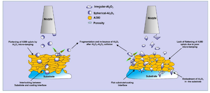
It has been widely accepted that for metallic powders, the initial kinetic energy of particles and deformability of materials are the major factors determining particle deposition and rebounding [32, 33]. However, for brittle alumina particles, the retention mechanisms are different depending on its morphology. Figure 9 shows the behavior of dissimilar alumina particles and their influence on coating characteristics during cold-spray process. For S-alumina, the deposition behavior and its micro-tamping effect during the cold-spray process can be illustrated as follows. At the first stage of deposition, the substrate was affected by the impact of alumina. The original flat surface assumed irregular (wavy) shape which facilitated efficient mechanical interlocking of A380 splats with the substrate. The wavy morphology of the substrate also results in high interfacial contact area which suggests good interfacial bonding between deposit and the substrate [34]. At the second stage, most of the S-alumina lacks the angularity needed to get mechanically anchored and rebounds after impact on the surface of the deposit layer, resulting in the increased degree of deformation and hardening of the impacted surface. The shape of the deposited A380 splats changed from ellipse to elongated strips. As a result, the bonding between splats is stronger and the defects at the boundary are minimized. It is very difficult for S-alumina particles to retain in the coatings because the S-alumina particles must break to obtain the angularity necessary to penetrate, or they have to get trapped between A380 particles. During continuous spraying process, a dense coating with a certain thickness is successfully prepared with the layer-by-layer deposition of A380 splats together with micro-tamping of the S-alumina particles. This provides the notion of fabricating thick and dense metallic components by adding hard spherical ceramic particles in the feedstock. For the feedstock containing I-alumina, the embedding effect is prevalent during the whole deposition process. The polygonal structure of I-alumina shows higher probability of embedding over S-alumina particles and helps to lock the particles in the A380 coatings upon impact. The more retained alumina particles in the coating are, the more likely it is to be impacted by the coming alumina particles. Therefore, the coating is composed of large amount of broken alumina fragments which result in more cracks/pores. Moreover, the alumina fragments at the interface resulted in significant degradation of interfacial bonding between the coating and the substrate. On the other hand, due to the increased content of hard ceramic phase, the coating can exhibit higher hardness. Hence, it may result in enhancement of other functional property (e.g., improved tribological properties, etc.).
Fig. 9 Schematic diagrams of deposition behavior for S- and I-alumina coatings
(1) S-alumina particles exhibited much better micro-tamping effect with very few particles retained in the final coating. As a result, S-Coatings show lower porosity, lower surface roughness and better interfacial bonding compared with I-Coatings. S-Coating 20 showed the lowest porosity value among all the coatings, which suggests that the optimum content of spherical alumina in the feedstock is 20 wt% when the S-alumina is used as a micro-tamping agent.
(2) In contrast, I-alumina particles showed embedding effect during deposition process with much higher deposition efficiency. Consequently, the hardness of the I-Coatings was much higher than those containing S-alumina. Notwithstanding, the porosity and the surface roughness of the coatings did not show any significant change. Compared with S-Coatings, much reduced level of mechanical interlocking was noticed at the I-Coating/substrate interface.
(3) Fragmentation of alumina particles was noticed in both types of composite coatings (in particular when the volume fraction of alumina was > 20% in the feedstock), and it resulted in high defect density in the coatings.
This work was financially supported by the National Natural Science Foundation of China (Nos. 51671205 and 51801217).
The authors have declared that no competing interests exist.

 WeChat
/
| 〈 |
|
〉 |


