

1 Introduction
The need for increasing size and carrying capacity of the space launch vehicles led to the extensive use of high-strength aluminum alloy structures which need to be welded with friction stir welding (FSW). FSW is a solid-state welding process which made stronger welded joints of aluminum alloys than that welded with conventional fusion welding technologies benefited from the lower welding peak temperatures [1]. In general, two difficult challenges received increasingly attention for the FSW of large-scale aerospace aluminum alloy structures: the in situ repair of the welding defects and filling the keyhole at the end of the weld seam [2, 3]. The repair technologies based on fusion welding processes, such as TIG and MIG, were not applicable for repairing the high-strength aluminum alloy FSW structures, because the welding thermal process might further decrease the strength of the heat affect zone (HAZ) and cause greater residual stress and distortion [4]. Therefore, a high-quality welding repair technology suitable for the large aluminum alloy-welded structures is desiderated.
Friction pull plug welding (FPPW) is a solid-state welding process proposed by TWI in the year of 1995 [5]. It exhibited remarkable advantages in filling the keyhole and repairing the weld defect formed in the FSW weld seam of the aerospace aluminum alloy structures [6]. As shown in Fig. 1, FPPW is in fact a hole-filling process which involves a through-hole machined primarily on the area needs to be repaired and a tapered aluminum alloy plug that specially designed to make high-quality bonding to the hole wall. The plug rotates with a very high rotational speed and needs to be pulled with a certain axial feeding speed or axial load to produce the frictional heat and the plastic flow of materials around the plug continuously. When the axial feeding distance of the plug reached the set point, the rotating stopped immediately, and then another axial pull force called forging force was imposed on the plug. At this point, the whole FPPW process was achieved [7].
Fig.1
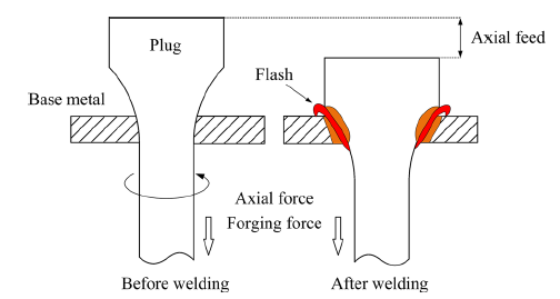
Fig.1
Schematic diagram of friction pull plug welding (FPPW)
Some of the researches confirmed the advantages of FPPW in repairing the aluminum alloy cylindrical tank of the launch vehicle and the spacecraft. Hartley and Coletta from Marshall Space Flight Center proved the applicability of FPPW for repairing the 2195 aluminum alloy sheet [8, 9]. Littell [10], Brooke and Bradford [11] conducted a further study concerning the influence of welding parameters on the bonding quality of the FPPW aluminum alloy joint. They found that, in order to obtain defect-free joints, an extremely high rotational speed was essential and the axial feeding of the plug should be strictly controlled. Metz's results also showed that the tensile strength and fatigue strength of the AA2195 FSW joint repaired by FPPW were nearly equal to that of the as-welded FSW joint [12]. Our previous results indicated that the plug with a circular arc shape was suitable for welding 6-8 mm thick 2219-T87 aluminum alloy sheet, and increasing the axial load could improve the bonding quality between the plug and the hole [13,14,15].
It should be noted that, since the weld geometry and welding parameters were optimized, the axial loading history and the change of axial force during FPPW also had significant influences on the weld qualities. Our previous results showed that the axial loading rate, which referred to the rate of the axial force increasing from the contact force value to the axial welding force setting, influenced the bonding strength between the plug and the plate significantly. Moreover, the axial feeding displacement of the plug was also critical for the formation of the lack of bonding defect. However, these aspects have not been studied previously. The present research focused on exploring the effect of the axial force changing on the weld formation and finding a feasible technical route to improve the welding quality.
2 Experimental Procedure
Several 5A06-H112 aluminum alloy (AA5A06-H112) sheets and rods were used as the base material and plug material for carrying out the FPPW experiment. The chemical composition of the AA5A06-H112 is given in Table 1. The hardness and tensile strength of the AA5A06-H112 sheets were 95 HV and 315 MPa, respectively. Figure 2 shows the details of the geometry parameters of the plug and the hole. Before welding, a straight through hole with a diameter of 28 mm was drilled on the AA5A06 plate sample with a dimension of 200 mm × 80 mm × 6 mm. The AA5A06 rods were machined into the plugs with a circular arc profile and threads as shown in Fig. 2a. The plate sample was clamped on the fixture, and the plug was placed through the hole and fixed with the plug holder by thread fastening.
Table 1 Chemical composition of 5A06-H112 aluminum alloy (wt%)
| Material | Mg | Si | Fe | Zn | Ti | Mn | Cu | Be | Al |
|---|---|---|---|---|---|---|---|---|---|
| 5A06-H112 | 6.8 | 0.4 | 0.4 | 0.2 | 0.1 | 0.8 | 0.1 | 0.005 | Bal. |
Fig.2
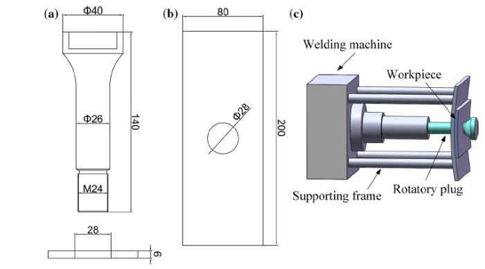
Fig.2
Details of material used in FPPW process, a, b the geometry parameters of the plug and the hole (mm), c schematic illustration of FPPW process
The welding experiment was carried out on TJU-145 FPPW equipment that developed by Tianjin University in the year of 2016. For the convenience of explanation, the whole process of FPPW was divided into five stages as illustrated in Fig. 3: startup stage, preheating stage, loading stage, stable welding stage with a constant axial force and forging stage. The welding parameters used in this study are given in Table 2. According to the results of our previous experiments [16, 17], the rotating speed of the plug was set as 7000 rpm to ensure sufficient heat generation. The axial welding force was ranged in 20-30 kN, and the axial forging force was equal to the axial welding force to maintain a good root formation. The influence of the axial loading rate (10-25 kN/s) on the weld quality was studied in Case 1. In Case 2 and Case 3, the influences of the axial welding force (5-7 mm) and axial feeding displacement (20-30 kN) on the weld performance were studied.
Fig.3
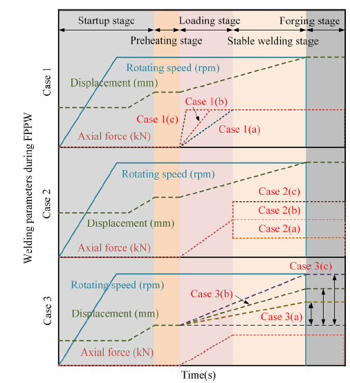
Fig.3
Welding parameters of 5A06 aluminum alloy FPPW
Table 2 Welding parameters of 5A06 aluminum alloy FPPW
| Sample | Rotating speed (rpm) | Axial feed displacement (mm) | Axial loading rate (kN/s) | Axial welding force (kN) | Forging force (kN) |
|---|---|---|---|---|---|
| CASE 1 | 7000 | 6 | 10 | 25 | 25 |
| 7000 | 6 | 15 | 25 | 25 | |
| 7000 | 6 | 20 | 25 | 25 | |
| CASE 2 | 7000 | 6 | 15 | 20 | 20 |
| 7000 | 6 | 15 | 25 | 25 | |
| 7000 | 6 | 15 | 30 | 30 | |
| CASE 3 | 7000 | 5 | 15 | 25 | 25 |
| 7000 | 6 | 15 | 25 | 25 | |
| 7000 | 7 | 15 | 25 | 25 |
After welding, the as-welded samples were cross-sectioned, mechanically polished and etched by Keller reagent (3 ml HCl, 5 ml HNO3, 2 ml HF, 190 ml H2O) for 15 s. Microstructure observations were conducted on OLYMPUS GX51 optical microscope (OM). SU1510 scanning electron microscope (SEM) was used to observe the second phase particle distribution of the weld. Tecnai G2F30 transmission electron microscope (TEM) and selected area electron diffraction (SAED) were used to characterize the grain structures and precipitates of the region nearby the bonding interface. 432SVD Vickers micro-hardness tester was used to examine the hardness distribution of the weld by applying 1000 g force and 10 s dwell time. Tensile test of the joint was carried out on CSS-44100 universal testing machine.
3 Results and Discussion
3.1 Weld Formation and Defect
Figure 4 shows the cross sections of the AA5A06 FPPW joints welded with different axial loading rates in CASE 1 welding trial with the welding parameters as list in Table 2. As shown in Fig. 4b and c, there was no welding defect in the as-welded joints when using a relatively high axial loading rate of 15 kN/s or 20 kN/s. As shown in Fig. 4a, when the axial loading rate was decreased to 10 kN/s, lack of bonding defects formed at the contact interface between the plug and the hole wall near the upper surface of the weld, as could be seen in Fig. 4d and e, respectively. It was found that lack of bonding defect was in fact a gap formed between the plug and the hole wall because of the insufficient heat generation and pressure on the frictional interface.
Fig.4

Fig.4
Cross sections of the joints welded with different axial loading rates, a 10 kN/s, b 15 kN/s, c 20 kN/s, d, e are the details of lack of bonding defects as marked in
The above results indicated that the change of axial loading rate in the loading stage of the FPPW process has an obvious effect on the bonding quality of joint, especially on the formation of the lack of bonding defect near the big end of the plug. It was believed that the increase in the axial loading rate results in the increase in heat production efficiency on the friction interface of the plug and the hole and shortens the time from loading stage to the beginning of the constant force welding stage, which were conducive to the uniformity and stability of temperature distribution and the sufficient plastic flow of materials around the plug.
The cross sections of the FPPW joints welded with different axial welding forces are shown in Fig. 5. The welding parameters complied with the experimental scheme of CASE 2 as shown in Fig. 3 and Table 2. As shown in Fig. 5a-c, all the joints were defect free within the thickness range of the plate, showing that the variation of axial welding force from 20 to 30 kN has not very obvious effect on the characteristics of weld formation when using a certain axial loading rate of 15 kN/s. It indicated that 5A06-H112 aluminum alloy has good weldability by FPPW in the range of suitable welding parameters benefited from its good plasticity at high temperatures [18]. Similar results were also obtained in the previous study which showed that the increase in axial welding force can promote the heat generation and enhance the metallurgical bonding of the plug and the plate during FPPW process.
Fig.5
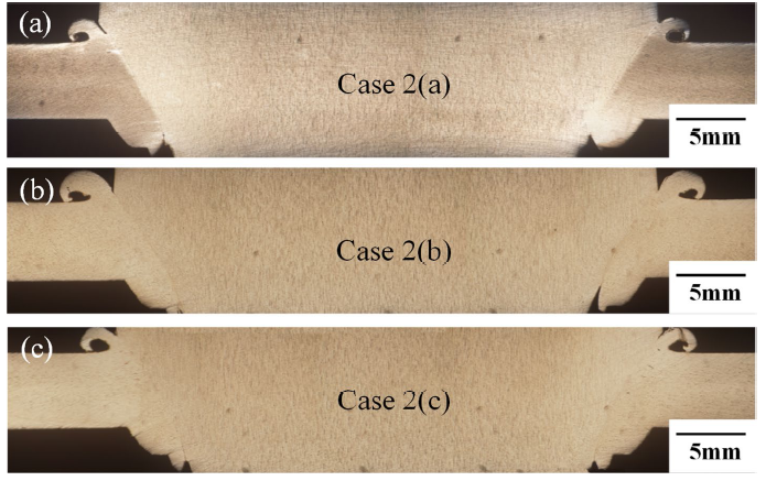
Fig.5
Cross sections of the joints welded with different axial welding force, a 20 kN, b 25 kN, c 30 kN
Figure 6 shows the cross sections of the joints obtained in CASE 3 and reveals the influence of axial feeding displacement of the plug on the bonding quality of the AA5A06 FPPW joint. As shown in Fig. 6a, lack of bonding defects formed in both the upper and the lower areas of the joint when welding with an axial feeding displacement of 5 mm. The details of the lack of bonding defects as marked in Fig. 6a are shown in Fig. 6d and e. It can be seen that the width of the gap in the upper end was wider than that in the lower end. When the axial feeding displacement was increased up to 6 mm and 7 mm, lack of bonding defect disappeared as can be seen in Fig. 6b and c. It indicates that the axial feeding displacement of the plug during FPPW process is also an important parameter needed to be controlled properly.
Fig.6

Fig.6
Cross sections of the joints welded with different axial feeding displacement, a 5 mm, b 6 mm, c 7 mm, d, e are the details of lack of bonding defects as marked in
3.2 Microstructural Evolutions
The microstructures of the AA5A06 FPPW joint observed under OM are shown in Fig. 7. The joint can be divided into five regions as marked in the overall morphology, namely plug material (PM), the base material (BM), heat affect zone (HAZ) and thermal mechanically affect zone (TMAZ) in BM and the recrystallization zone (RZ) in BM side adjoining to the bonding interface as shown in Fig. 7a-f. Moreover, there is no significant difference between the as-welded microstructure of HAZ in PM side and the initial microstructure of the PM even in the region which is very close to the frictional interface. Such characteristic was similar to that observed in AA2219 FPPW joint in our previous study and the main reason was believed as that the welding peak temperature in PM side was very low and the welding process was completed in a very short time [17].
Fig.7
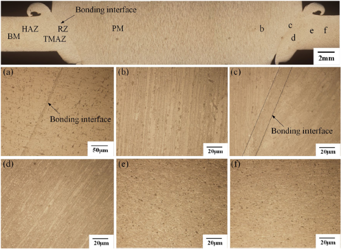
Fig.7
Microstructure in different regions of the joint welded in Case 1(b): a bonding interface, b PM, c RZ, d TMAZ, e HAZ, f BM
As shown in Fig. 7a, a banded structure can be observed along with the bonding interface of the plug and the hole wall. The higher magnification morphology of this zone reveals that, as shown in Fig. 7c, the banded structure consists mainly of fine equiaxed crystal grains. Therefore, this region was named as recrystallized zone (RZ) in the present study. It indicated that under the action of friction heating and extrusion forming from the plug to the hole wall, severe plastic deformation occurred in a very narrow region in the base material that very close to the bonding interface and led to the dynamic recrystallization of the grains in this region.
As compared from Fig. 7b and c, the characteristic of the grains within the PM close to RZ was similar to that of the PM, which was elongated parallel to the extruding direction of the rod. Figure 7d shows the grain structures of the TMAZ in BM side close to RZ. It can be seen that the original grains of BM adjoining to the bonding interface were grown larger and elongated and flowed downward along with the arc of the plug after FPPW. As shown in Fig. 7e and f, in HAZ where is a little farther from the bonding interface, the crystalline grains and the grain boundary second phase particles were larger than that in BM.
To investigate the distribution features of the second phase particles in the joint, SEM and TEM characterizations of the key regions of the FPPW joint were conducted. The results are shown in Figs. 8 and 9, respectively. As shown in Fig. 8a and f, in PM and BM, there were several large second phase particles distributed uniformly at the grain boundaries before welding. However, as can be seen in Fig. 8b-d, these second phase particles distributed continuously along with the two edges of RZ after welding. Moreover, in TMAZ, the second phase particles were observed at the grain boundaries with tracing the direction of the material flow. According to the analysis results of EDS (Fig. 8g) and SAED (Fig. 9a-c), these second phase particles were identified as Al6FeMn phase and Al3Mg2 phase, which can be found 5A06 aluminum alloy frequently [19, 20]. It was also found that the Al6FeMn particles were disk shaped, while the Al3Mg2 particles were rod shaped. Most of the Al6FeMn particles were larger than the Al3Mg2 particles.
Fig.8
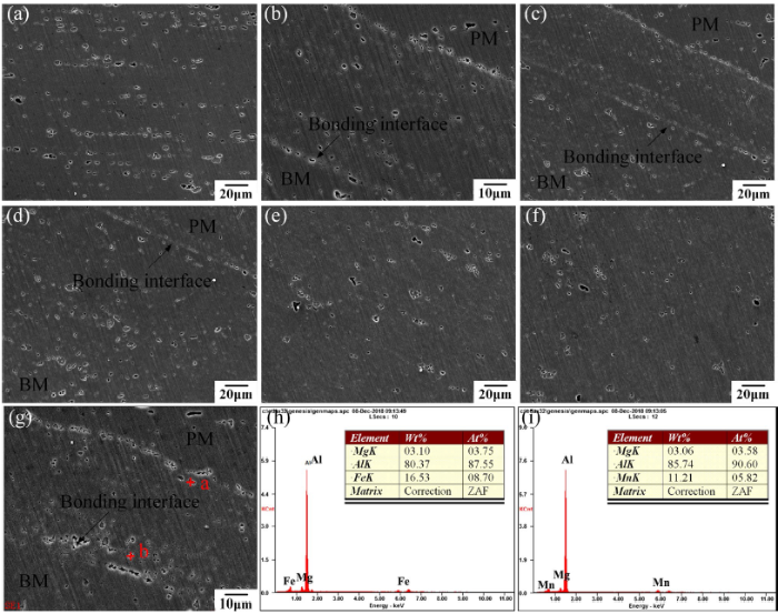
Fig.8
Second-phase particles in different regions of the joint: a PM, b RZ, c bonding interface, d TMAZ, e HAZ, f BM, g EDS of particles near the bonding interface, h EDS results of particle a, i EDS results of particle b
Fig.9
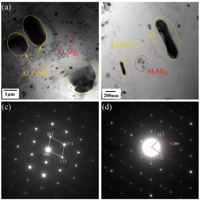
Fig.9
Morphologies of second particles at the BM and bonding interface of the joint: a second particles at the BM, b second particles near the bonding interface, c diffraction pattern of Al6FeMn, d diffraction pattern of Al3Mg2
The above observations indicated that FPPW process could not change type and the morphology of the second phase particles in 5A06 aluminum alloy, but could result in the redistribution of them especially along with the bonding interface and in the TMAZ where plastic flow occurred during welding. The Al6FeMn and Al3Mg2 particles observed in 5A06 aluminum alloy were formed in the casting because of the solute redistribution during the solidification process. These particles were hard and very difficult to dissolve into the matrix during the solid-state processing process. During FPPW process, these hard second phase particles might flow with the material flow and distributed continuously along with the bonding interface between the plug weld and the hole wall. It should be noted that once the hard second phase particles aggregated and grown larger, both strength and ductility of the alloy might decrease obviously.
3.3 Hardness Distribution
Figure 10 shows the typical hardness distribution of the AA5A06 FPPW joint. As can be seen in Fig. 10 that when testing the hardness distribution of the weld from BM to TMAZ a trend of decrease can be obtained, and the lowest hardness value of 92.3 HV was found in TMAZ adjoining to RZ. When the testing point entered the RZ, the hardness value increased with getting close to PM. It was supported that both the recrystallization and dissolution of work hardening caused by thermal process resulted in the reduction in hardness value in TMAZ. And the fact that the growth of grains also further decreased the hardness and led to that the TMAZ close to RZ was the weakest region of the joint. Besides, as discussed previously, inconspicuous growth of the second phase particles named Al6FeMn and Al3Mg2 was observed in TMAZ. Thus, it was believed that those particles exhibited no significant strengthening effect on the hardness of TMAZ [19]. On the contrary, the aggregated distribution of those second phase particles near the bonding interface might lead to the occurrence of yield and fracture in the subsequent tensile test.
Fig.10
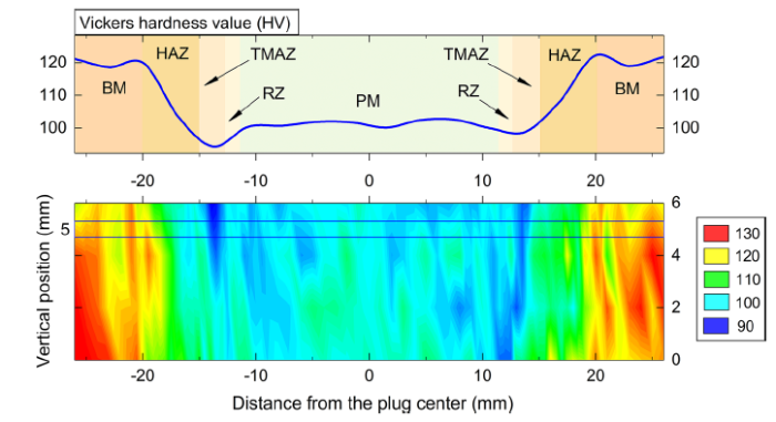
Fig.10
Hardness distribution of 5A06 FPPW joint welded with the parameters used in Case 1(b)
3.4 Tensile Properties
The ultimate tensile strength (UTS) and elongation of the FPPW joints welded with different axial loading rates are shown in Fig. 11. It can be found that both of the UTS and elongation of the joint increased with the increase in the axial loading rate. The highest UTS and elongation, which were 314 MPa and 4.8%, respectively, were obtained on the sample welded with an axial loading rate of 20 kN/s. However, the joint welded with an axial loading rate of 10 kN/s had the lowest UTS and elongation.
Fig.11
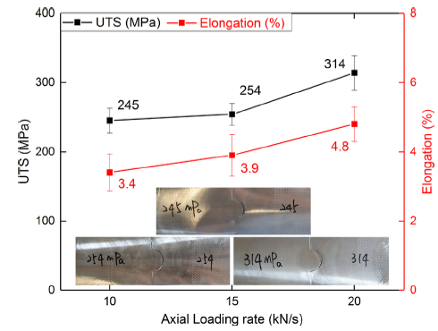
Fig.11
UTS and elongation of the joints welded with different axial loading rates
Basically, the formation of lack of bonding defect formed along with the bonding interface under lower axial loading rates resulted in the reduction in the strength joint. Moreover, the lack of bonding defect was eliminated when the increase in the axial loading was 15 kN/s, but the UTS of the joint was also lower than that of that welded with 20 kN/s. It indicated that although no welding defect formed along with the bonding interface, the axial loading rate has an obvious effect on the bonding strength of the plug and the hole wall. Besides, the increase in the axial loading rate led to shorter time to perform the whole FPPW process, indicating that the heating time for TMAZ was reduced. Therefore, the degree of the softening of TMAZ can be reduced when welding with a relatively high axial loading rate.
Figure 12 shows the UTS and elongation of the joints welded with different axial welding forces. It was found that the UTS and elongation of the joint welded with 20 kN axial welding force were 240 MPa and 2.9%, respectively. However, both of the UTS and elongation of the joint were improved with the increase in the axial welding force. As discussed in the above sections, although all the three FPPW joints welded with the axial welding force of 20-30 kN were defect free, they showed different UTS and elongations and different fracture characteristics. It indicated that the axial welding force also had a significant influence on the bonding quality of the joint. It was believed that the improvement in the bonding quality was close related to the higher extruding stress when the axial welding force applied on the plug axially was increased during FPPW process.
Fig.12
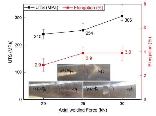
Fig.12
UTS and elongation of the joints welded with different axial welding forces
Figure 13 reveals the UTS and elongation of the joints welded with different axial feeding displacements. Obviously, the joints fabricated with the axial feeding displacement of 5 mm exhibited lower UTS and the elongation than that welded with the axial feeding displacement of 6 mm, for which the UTS and elongation were 211 MPa and 3.4%, respectively. As mentioned above, the poor tensile property of the joint was caused by the existence of lack of bonding defect near the upper and the lower surface of the joint. However, when the axial feeding displacement was increased to 7 mm, UTS of the joint decreased to 244 MPa, a small reduction comparing to that of 254 MPa UTS for the joint welded with 6 mm axial feeding displacement. It was believed that the increasing axial feeding displacement also resulted in the more reduction in work hardening and severer coarsening of grains, because a longer frictional heating time was needed.
Fig.13
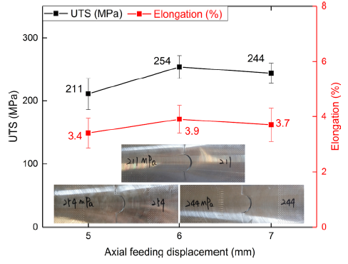
Fig.13
UTS and elongation of the joints welded with different axial feeding displacements
3.5 Fracture Morphology
The SEM morphologies of fracture surfaces on the typical failure samples are shown in Fig. 14. A lot of dimples with different sizes were observed on the fracture surfaces for all the joints. It indicated that the metallurgical bonding was achieved between the plug and the base material. Furthermore, to FPPW which involves both frictional heating and mechanical deformation of the materials, there were some second particles distributed at the bottom of the dimples as the core of crack initiation during tensile deformation. Taking a comparison of Fig. 14a and b, the smaller dimples were observed on the fracture surface of the joint failed with the UTS of 254 MPa, revealing that the plasticity of the joint was not as good as that with the UTS of 306 MPa. As shown in Fig. 14c, the features of partial brittle fracture marked by the red circle were also observed on the fracture surface of the joint, indicating that the bonding quality of the joint was not as good as the joint welded with higher axial loading rate and axial welding force.
Fig.14
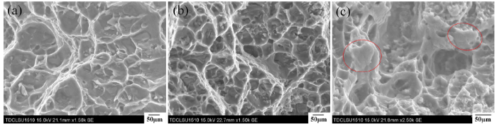
Fig.14
Fracture morphology of joints failed with different strengths: a Case 2(c), b Case 2(b), c Case 3(a)
4 Conclusions
In this study, the influence of axial force control strategy on the weld formation and mechanical properties of the 5A06 aluminum alloy FPPW joints were investigated. The main results are as follows:
(1) The FPPW joints without any defects could be made with the welding parameters of 15-20 kN/s axial loading rate, 20-30 kN axial welding force and 6-7 mm axial feeding displacement. When the axial loading rate was lower than 15 kN/s, or the axial feeding displacement was shorter than 6 mm, lack of bonding defect might form along with the bonding interface.
(2) Increasing axial loading rate and axial welding force promoted the heat generation and reduced the time to complete the whole FPPW process. Moreover, increasing the axial feeding displacement improved the extent the plastic flow of the materials. The above characteristics benefitted the improvement in the weld quality and mechanical properties of the joint.
(3) The thermal mechanically affect zone (TMAZ) had the lowest hardness value throughout the joint and was found as the fracture location to all the tensile samples. The softening of TMAZ was caused by the weakening of the cold work hardening and the grain growth. With increasing the axial loading rate and axial welding force, both the strength and ductility of the joints can be improved. The maximum ultimate tensile strength and elongation of the FPPW 5A06 joints were 314 MPa and 4.8%, respectively.
Acknowledgements
This work was financially supported by the Science and Technology Program of Tianjin (Granted No. 18ZXCLGX00060), and the National Natural Science Foundation of China (Granted No. 51875401). Great thanks are given to Capital Aerospace Machinery Corporation for supporting the materials.
Reference
- About AMSE
- Authors and reviewers
- Contact
E-mail: ams@imr.ac.cn
Address: 72 Wenhua Road, Shenyang, Liaoning, 110016, China
 WeChat
- Copyright © Editorial Office of Acta Metallurgica Sinica (English Letters), All Rights Reserved.
