Search for articles:
Juan Hou , Xiang-Xi Ye
Corresponding authors:
Received: 2018-06-27
Revised: 2018-08-3
Online: 2019-03-10
Copyright: 2019 Editorial board of Acta Metallurgica Sinica(English Letters) Copyright reserved, Editorial board of Acta Metallurgica Sinica(English Letters)
More
Abstract
Corrosion test of a Ni-16Mo-7Cr alloy with a decarburized layer was conducted in FLiNaK salt at 700 °C. A detailed microstructure study was performed to investigate the corrosion behavior and mechanisms. The results show that the Fe-rich layers were formed on the corroded alloys with and without decarburization. The surface decarburization had little influence on the corrosion resistance of the alloy, whereas it caused more M2C carbide formation beneath the corrosion layer. That is attributed to the higher concentration of C gradient near the alloy surface, which was resulted from the increase in C content liberated from graphite crucible wall during the corrosion process.
Keywords:
Nuclear power is considered to be the best choice to satisfy the demand of future energy in environmental protection, fuel economy, saving cost, etc. The molten salt reactor (MSR) has been selected as one of the most promising next-generation nuclear reactors, due to its incomparable advantages for online refueling and removing fission products, good heat transfer characteristics, high security, along with hydrogen production capability [1, 2, 3]. The eutectic molten fluoride salt is widely used as fuel carrier and coolant medium in MSR to transfer heat from nuclear reactors to plants. However, the molten fluoride is highly corrosive at high temperature and could cause severe material degradation. The inevitable presence of impurities formed during the manufacture, transfer and handling process of molten salts, such as oxides, hydroxide and polyvalent metallic ions (Ni2+, Zr2+, Fe2+), could act as the principal driving force in the initial corrosion stage and significantly accelerate the materials corrosion [4, 5, 6, 7]. Therefore, the structural materials, which directly contacted the molten salt in MSR, need to possess excellent corrosion resistance besides good mechanical properties.
A Ni-16Mo-7Cr-based superalloy, named as GH3535 (see the composition in Table 1), was developed for the application in thorium-based molten salt reactor (TMSR) as the main structure materials, such as reactor internals, heat exchangers, pumps and piping. Fan et al. [8, 9] studied the oxidation behavior of this alloy at the temperature range of 700-980 °C and confirmed that it was completely antioxidant at 870 °C. That is attributed to the minimum but sufficient Cr content in the alloy. Liu et al. [10, 11] investigated microstructure and stress rupture properties of GH3535 nickel-based superalloy during long-term thermal exposure at 700 °C. It has been proved that the alloy has good stress rupture properties related to the secondary carbides precipitated along grain boundaries. And more importantly, GH3535 alloy has excellent corrosion resistance to molten salt [12, 13]. Nevertheless, some abnormal microstructures generated during the fabrication process are detrimental to the alloy. Among these, the decarburization layer formed beneath the oxidation scale when the alloy subjected to solution heat treatment in air is a typical one. It is inevitably formed after heat treatment in oxidizing atmosphere at high temperatures [14, 15]. The reason for the decarburization layer formation is mainly attributed to the reaction between carbon from steel substrate and oxidizing agents such as CO2, H2O and H2 in the environment atmosphere. The decarburization leads to the lower concentration of carbon in the subsurface of alloy and could decrease the surface hardness, wear endurance and fatigue strength of the materials, resulting in remarkable lifetime reduction [16, 17, 18]. A couple of technologies have been developed to prevent the detrimental effects of decarburization, including applying superficial coating on the surface before heat treatment [14], introducing a protective atmosphere [16], and mechanical-based removing techniques [19]. However, none of the above technologies are applicable to GH3535 alloy due to its complexity of the fabrication process. The decarburization phenomenon could not be avoided during the manufacture and forming of alloy component.
Table 1 Actual chemical compositions of alloy used in this study (wt%)
| Ni | Mo | Cr | Fe | Mn | Si | C | Impurity element (ppm) | |||
|---|---|---|---|---|---|---|---|---|---|---|
| S | P | O | N | |||||||
| Bal. | 17.3 | 7.0 | 3.9 | 0.60 | 0.45 | 0.055 | < 10 | < 20 | 11 | 10 |
In the decarburization layer, the C element lost from the matrix will result in the microstructural change near the surface, such as the grain coarsening, the main element segregation and the disappearance of carbides [14]. It has been accepted well that the dominant corrosion process of Ni-based alloy with Cr containing in FLiNaK salt is the diffusion and dissolution of Cr from metal matrix into the melt, while whether the Cr diffusion behavior would be affected by the microstructural evolution is unclear yet. And there are few efforts made to classify the influence of decarburization on the corrosion in molten fluorides. Accordingly, it is necessary to evaluate and study the effect of decarburization on corrosion performance of GH3535 alloy.
In this work, the effect of surface decarburization on the corrosion behavior of GH3535 alloy was investigated at 700 °C in eutectic FLiNaK molten salt. Different depths of decarburization layers were obtained by applying various heat treatment processes to GH3535 alloy. After the corrosion tests, the surface morphology, microstructure and corrosion depth of corroded specimens were analyzed in order to understand the mechanism of decarburized layer for corrosion behavior of GH3535 alloy.
The actual chemical composition (wt%) of the investigated alloy is listed in Table 1. The alloy ingot was prepared in a vacuum induction melt furnace (VIM) and then hot-forged into bars in the temperature range of 1150-1200 °C with a diameter of 16 mm.
Corrosion coupons with a size of 15 mm × 10 mm × 2 mm were then cut from these bars. In order to obtain different depths of decarburized layers, two heat treatment processes were applied to the coupons: (1) solution treatment at 1177 °C for 2 h followed by water quenching (alloy 2, with decarburization layer ~ 400 μm); (2) solution treatment at 1177 °C for 6 h followed by water quenching (alloy 3, with decarburization layer ~ 750 μm). The coupons were then mechanically ground by SiC paper up to 1000 grits followed by polishing with 0.05 μm Al2O3. Coupons without decarburization were directly cut from the heat-treated hot rolling bars for comparison testing (alloy 1). All the prepared specimens were ultrasonically cleaned in ethanol. The dried coupons were kept in glove box under Ar atmosphere before corrosion tests. Surface treatment conditions for the specimens used in this study are listed in Table 2.
Table 2 Contents of trace impurities in as-received FLiNaK before exposing test (unit: ppm; mg/kg)
| Fe | Ni | Cr | Mn | Mo |
|---|---|---|---|---|
| 149.5 ± 7.5 | 60.8 ± 10.4 | 26.3 ± 0.6 | 12.9 ± 0.4 | 21.4 ± 3.0 |
Each composition value is averaged over six data, expressed in terms of a mean and standard deviation The purified FLiNaK salt (LiF, NaF, KF of 46.5, 11.5, 42 mol%, respectively) with lower H2O content (H2O content < 10 ppm) was selected for this corrosion test. The trace impurity of the as-received FLiNaK salt was analyzed by inductively coupled plasma-optical emission spectroscopy (ICP-OES), as given in Table 2.
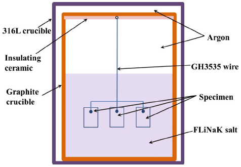
The schematic diagram of corrosion test equipment is shown in Fig. 1. The isopressing graphite (CDI-1A) with a purity of 99.99% was used as the inner container for its intrinsic inertness to FLiNaK. To avoid the galvanic corrosion, the test coupons were electronically isolated from the graphite container using an insulating ceramic slice and were fixed on a GH3535 fixing wire. Then, they were put into the graphite crucible containing FLiNaK salt of 270 g. The 316L stainless steel was used as shield cover to reduce oxidation of the graphite crucibles at high temperature. The graphite crucible covered with a graphite lid was placed in the chamber and then was shut by welding. All the above operations were conducted in a glove box under Ar atmosphere to avoid the introduction of impurities of H2O and O2. The prepared test chamber was placed into a high-temperature furnace for exposure at 700 °C with a fixed duration of 400 h. After the exposure, the specimens were taken out from the crucible and cleaned in 1 mol/L Al (NO3)3 solutions to dispose the residual FLiNaK salt. The cleaned coupons were then rinsed in alcohol and deionized water and dried for the following analyses.
Fig. 1 Schematic of experimental equipment
The microstructure observation of the GH3535 alloy before and after corrosion was analyzed by optical microscopy (OM), scanning electron microscope (SEM) equipped with an energy-dispersive spectroscopy (EDS), X-ray diffractometer (XRD), electron probe microanalyzer (EPMA) and a FEI Tecnai G2 F20 transmission electron microscopy (TEM). The samples for TEM observation were prepared by a focus ion beam (FIB) machine with the thickness of 83 nm.
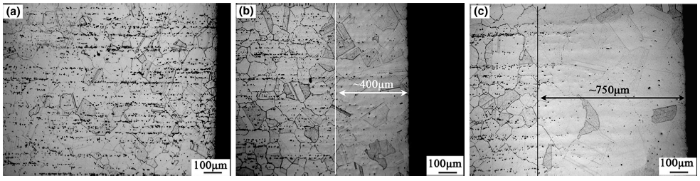
Figure 2 shows the cross-sectional morphologies of the alloys with different heat treatment processes. For the alloy 1, as shown in Fig. 2a, the equiaxed grain with a size of around 70 μm was observed. The chain-like particles distributing along the roll direction precipitated during the solidification have been identified as M6C carbides in a previous research [10]. No obvious diversity was observed in metallography in the surface layer in the as-received GH3535 without decarburization. In the alloy 2, a decarburization layer with a depth of ~ 400 μm, which was defined as the coarsening grain layer in this study, was formed beneath the outmost surface (as shown in Fig. 2b). The grain size was grown to ~ 200 μm, and the number of carbides was dramatically decreased in the decarburization layer. With prolonged heat treatment time, the depth of decarburization layer in alloy 3 was increased to around 750 μm, and the grain size near the surface was grown to ~ 350 μm as shown in Fig. 2c. The holding time of the heat treatment influenced the metallurgical microstructure apparently near the surface, exhibiting coarser grains and almost disappeared carbide spots.
Fig. 2 Microstructures of a alloy 1, b alloy 2, c alloy 3 with different surface condition
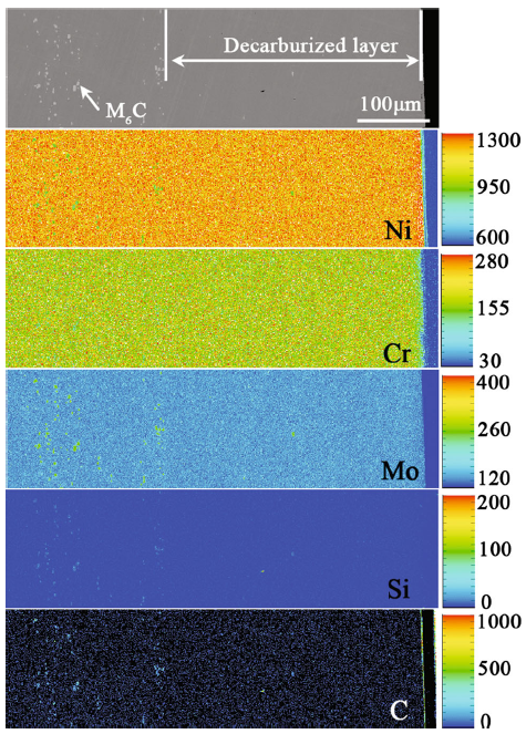
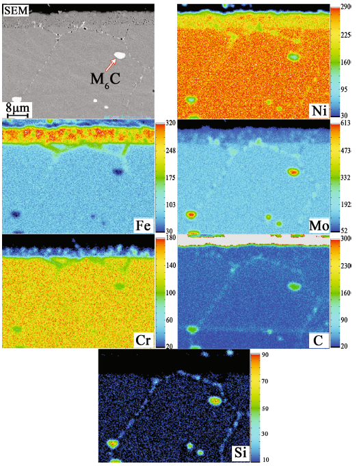
The composition distribution of the alloy 2 with decarburized layer was analyzed by EPMA map scanning, as shown in Fig. 3. An amount of M6C carbides enriched with Ni, Mo, Si and C elements were dispersed in the substrate, while only a few in the decarburized layer. No obvious segregation for the main alloying elements was observed in the decarburized layer.
Fig. 3 Cross section morphology and element distributions of alloy 2 after heat treatment at 1177 °C for 2 h (the color bar represents the degree of element enrichment)
3.2.1 XRD Analysis
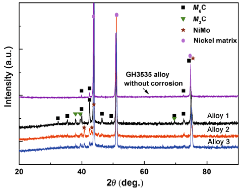
Figure 4 shows the XRD patterns of the corroded samples with and without decarburization layer. Compared with the as-received GH3535 alloy, M2C was detected after corrosion on the surface of all tested coupon. This is attributed to the corrosion process at 700 °C for 400 h duration, which acted as heat treatment in molten salt and resulted in the formation of the new phase M2C. However, in both alloy 2 and alloy 3, M6C precipitates completely disappeared, which is consistent with the metallurgical observation in Fig. 2.
Fig. 4 XRD analysis for surfaces of alloy 1, alloy 2, alloy 3 after corrosion
3.2.2 Microstructure Observation
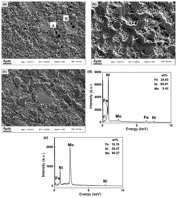
The surface morphologies of the specimens corroded at 700 °C for 400 h in FLiNaK salt were observed by SEM, as shown in Fig. 5. It was found that the corrosion products on surface of all coupons were composed of granular-like particles and lamellar particles. The distribution and dimension of these two kinds of corrosion products varied in the three alloys. The size of these particles in the samples with decarburization layer was large. EDS analysis further confirmed that granular-like particles were enriched in Ni and Fe (marked as “A” in Fig. 5a) and the lamellar particles were enriched in Ni and Mo elements (marked as “B” in Fig. 5a).
Fig. 5 Surface morphologies of a alloy 1, b alloy 2, c alloy 3 after corrosion at 700 °C for 400 h in FLiNaK salt and EDS analysis for d point A and e point B in a
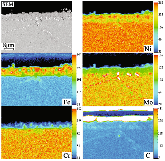
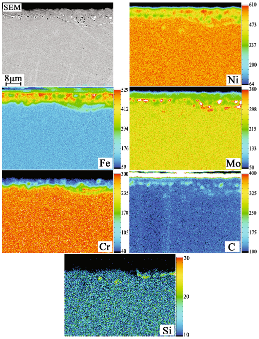
Cross sections of the corrosion layers were examined by EPMA, as shown in Figs. 6, 7 and 8. In alloy 1, as shown in Fig. 6, the thickness of the corrosion scale was ~ 7 μm. A number of pits and voids were observed in the corrosion scale and at the grain boundaries underneath the surface. EPMA mapping analysis indicated that the corrosion scale was enriched in Fe but depleted in Ni, Mo and Cr. The particles precipitated at the grain boundary had a size of ~ 200 nm and were enriched in Mo and C. The absence of Cr in the out layer suggested the occurrence of significant Cr dissolution during the corrosion process. In alloys 2 and 3 (as shown in Figs. 7 and 8), a large amount of particles enriched in Mo and C with a size from dozens of nanometers to a few microns were formed on the interface between the corrosion layer and substrate, while there were few such particles in alloy 1. The primary M6C carbides were not observed beneath the corrosion layers in alloy 2 and alloy 3, primarily due to the role of a thicker decarburized layer. This is in agreement with the results shown in Fig. 4.
Fig. 6 Cross section morphology and element distributions of alloy 1 after corrosion at 700 °C for 400 h in FLiNaK salt
Fig. 7 Cross section morphology and element distributions of alloy 2 after corrosion at 700 °C for 400 h in FLiNaK salt
Fig. 8 Cross section morphology and element distributions of alloy 3 after corrosion at 700 °C for 400 h in FLiNaK salt
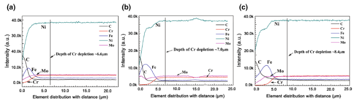
Considering the significant role of Cr depletion in molten salt corrosion, the surface layer with Cr depletion is correlated with the corrosion depth. The element distribution profiles of the three corroded samples analyzed by EPMA are shown in Fig. 9. In each corroded samples, linear scanning was conducted at least three times and then the profiles were averaged into a final element profile. From the element distribution profiles, the Ni, Cr, Mo and C concentrations near the surface are quite lower than those near the substrate, while the Fe concentration shows a reverse trend. The Cr depletion distances are around 6.6 μm, 7.0 μm and 8.4 μm for alloy 1, alloy 2 and alloy 3, respectively. It is indicated that the surface decarburization has little impact on the Cr leaching out from substrate to the molten salt, and just only results in minus increase in Cr depletion in decarburized alloy.
Fig. 9 Cr element distributions of a alloy 1, b alloy 2, c alloy 3 from surface to substrate after corrosion at 700 °C for 400 h in FLiNaK salt
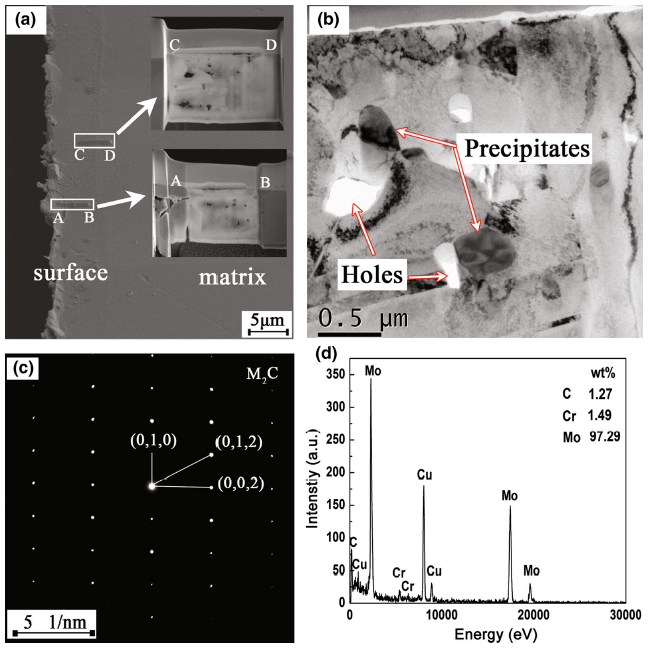
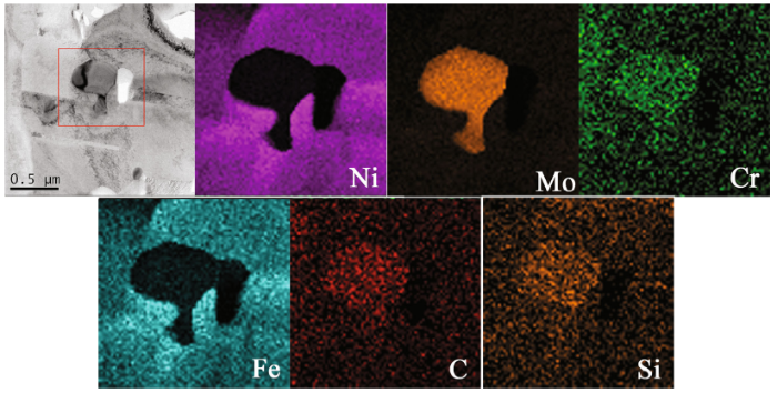
The newly formed phase observed on the interface between the corrosion layer and substrate in Figs. 7 and 8 was identified by selected area electron diffraction (SAED). Figure 10 shows the TEM analysis in the cross section of corroded alloy 3. The cross section of the coupon was milled into two parts by FIB: the surface area (closest to the surface, marked as “AB” in Fig. 10a) and the subsurface area (5-6 μm away from the surface, marked as “CD” in Fig. 10a). The precipitate was identified as Mo2C carbide by SAED and formed around the holes resulted from corrosion (as shown in Fig. 10b, c). It was enriched in Mo as analyzed by EDS (as shown in Fig. 10d). Figure 11 shows the element mapping of Mo2C precipitate observed in Fig. 10b. It could be seen that Mo, Cr, Si and C elements were enriched in the Mo2C carbides, while Ni and Fe elements were relatively enriched around them. Thus, Mo2C should be modified as (Mo, Cr)2(C, Si), which was abbreviated as M2C in this study.
Fig. 10 TEM analysis for alloy 3 corroded at 700 °C for 400 h in FLiNaK salt: a FIB-SEM image and sampling position; b TEM image of subsurface area (5-6 μm away from surface, marked as “CD” in a; c SAED pattern for precipitates shown in b; d EDS analysis for precipitates shown in b
Fig. 11 TEM image and element distribution maps of rectangle area for alloy 3 corroded at 700 °C for 400 h in FLiNaK salt
In the condition of static fluorides corrosion, the main driving force is the impurities in the molten salt, such as hydroxides, metal ions and oxides [20]. The corrosion products formed on the sound alloy/molten salt interface in fluoride molten salt are soluble, and no passive films are formed. Therefore, the corrosion lies directly on the dissolution of active components of the alloy into the molten salt. Cr is the most active one in metal alloying elements. Therefore, Cr is selectively attacked due to the highly negative Gibb’s free energy of its fluoride phase (CrF2 < FeF2 < NiF2 < MoF3) [7]. The corrosion behavior of Ni-Mo-Cr-based superalloy in FLiNaK molten salt has been investigated in the previous literatures [4, 12, 21, 22, 23]. It has been accepted that the dominant corrosion process of Cr-containing alloy in molten fluorides is mainly controlled by the diffusion of Cr from matrix into melt. In the corrosion process, the dissolution of Cr into melt includes two steps: Firstly, Cr is diffused to surface from interior bulk. The corrosion rate is essentially controlled by this step. Secondly, when the Cr reaches the surface, Cr is oxidized as Cr2+ by impurities and then dissolved into the melt. Cr2+ is subsequently disproportionated into Cr3+ and Cr0. Cr2+ and Cr3+ are two main states of chromium in molten fluorides, while Cr3+ is more stable than Cr2+ in FLiNaK salt. The corrosion could be rapidly accelerated by impurities until the impurities are depleted in a sealed vacuum condition [20]. The depletion of Cr from the matrix leads to the formation of pitting and voids near the surface. Therefore, the Cr diffusion in the alloy substrate is the radically rate-determining step of corrosion in this work [7, 21, 24, 25].
According to the metallurgical observation, the most dominant diversities between the samples with and without decarburization are the grain size, C content and precipitate distribution in the near surface. The coefficient of Cr self-diffusion in nickel-based alloys (D) obeys the Arrhenius relationship:
D=D0e-Q/(RT), (1)
where D0 is the pre-exponential factor, Q is the activation energy, R is the universal gas constant, and T is the temperature. The diffusion of Cr in polycrystalline metals is comprised of two main distinct processes, namely diffusion along grain boundaries and diffusion through the grain matrix. The effects of these two processes on the overall diffusion coefficient are not separated due to the complexity of microstructure in metals. The lattice diffusion and grain boundary diffusion have been investigated by many researchers. Their results demonstrate that lattice diffusion is dominant in the near-surface layer and grain boundary diffusion is predominant in substrate where Cr concentration is close to the initial content [26, 27, 28]. Wang et al. [29] have investigated the corrosion behavior of Ni-Cr alloys with various grain sizes in molten FLiNaK and reported that grain refinement remarkably accelerated the dissolution of Cr, leading to the formation of a wider Cr-depleted zone. That means the decreasing area and volume fraction of grain boundary might mitigate the corrosion attack. However, the different grain size in three alloys does not cause significant differences in Cr depletion depth, as illustrated in Figs. 6, 7, 8 and 9. The variation in corrosion depth is very small in this study, and the Cr depletion depth is much less than the grain size (~ 70 μm) and the decarburized layer depth (≥ 350 μm). That may be attributed to the insufficient corrosion time in this study.
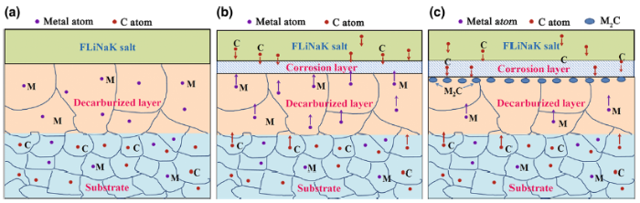
Although the decarburization has little influence on corrosion resistance of the alloy, it should be noted that more M2C type carbides were formed on the interface between corrosion layer and substrate in the decarburized samples. The schematic of M2C formation is shown in Fig. 12. During the corrosion process, the carbon liberated from graphite crucible wall was dispersed into the melt and caused the increment of C content in molten salt medium. The inwardly diffusing carbon reacted with the outwardly diffusing metal elements and then formed carbide particles in the alloy. Zheng et al. [30] also confirmed the Mo2C, Cr7C3 and Al4C3 carbides were formed in 316 stainless steel when was corroded in molten FLiBe salt in graphite crucible. It has been determined that the M2C carbide would be easily formed during thermal exposure in Ni-Mo-Cr superalloy without silicon [31, 32]. For GH3535 alloy, the Si element in the near surface has been consumed, as well as C during decarburization. Thus, M2C carbide is easier to form in this layer during the corrosion process. The higher concentration gradient of C on the surface of decarburized alloy could also provide more C atoms to form M2C rather than M6C. Zheng [33] compared the corrosion behavior of Hastelloy N samples tested in FLiBe salt in pure nickel and graphite corrosion capsules, respectively, and found that Cr23C6 was formed in the near-surface layer of the sample in the graphite capsule. He considered that the formation of the highly stable Cr23C6 appeared to stabilize Cr in alloy from dissolving in the molten FLiBe and might provide an engineering solution to mitigate corrosion in Hastelloy N in the long term. However, in this study, the M2C rather than C23C6 was found in the near-surface sample. Mo is the main element to form M2C. Thus, it can be inferred that the newly formed M2C carbide could mainly stabilize Mo by the mean of chemical bonding with carbon. It has been known that the corrosion of GH3535 goes on mainly by the preferential dissolution of Cr. Therefore, the formation of M2C plays a smaller role in mitigating the corrosion process of the alloy.
Fig. 12 Schematic of M2C formation in decarburized layer: a microstructure and element distribution before corrosion test; b diffusion direction of elements during corrosion process; cM2C formation beneath corrosion layer
In addition, in our previous research, M2C carbide is also a kind of metastable phase in Ni-Mo-Cr superalloy with high Mo content. It will be decomposed with the increase in aging time at 700-800 °C by the reaction as follows [31, 34]:
M2C→2M+C. (2)
Though the decomposition of M2C is not observed in this study due to short-term corrosion, the dissolved metal and C atoms could change the element distribution near the surface and accelerate the corrosion rate of the alloy in FLiNaK salt. On the other hand, the newly formed precipitates would act as defects due to the formation around the voids. That would possibly provide fast diffusion path for metal elements and thus accelerate the corrosion during longer corrosion process. From the results shown in Fig. 9, a tiny increase in Cr depletion depth in decarburized alloy can prove that. However, longer periods of corrosion tests should be carried out in the future work to identify change of corrosion property for decarburized alloy.
The formation of Fe-rich layer on the surface is also observed in all coupons in this study. Ye et al. [21] thoroughly discussed the reason for the Fe-rich layer formation in Ni-16Mo-7Cr-based alloy in FLiNaK salt. It is explained by the continuous reaction between Fe2+ in the FLiNaK salt and Cr in the alloy. In this study, the used molten salt for corrosion is as same batch as that in Ref. [36]. Therefore, the formation of Fe-rich layer is all attributed to the high impurities of Fe in the molten salt. In addition to Fe impurities, the influence of moisture on the corrosion behavior of Ni-based alloys in molten FLiNaK salt could not be neglected. On the surface of alloy after corrosion, Ni and Mo are also depleted from the Fe-rich layer (as shown in Figs. 6, 7 and 8). That is because Ni and Mo could react with HF, which is derived from the reaction between the slight trace amount of H2O and F- irons in FLiNaK salt [21, 35, 36].
1. Static corrosion tests for the alloys with decarburized layer were carried out at 700 °C for 400 h. The surface decarburization had little impact on the corrosion resistance of GH3535 alloy, only leaded to tiny increase in Cr depletion depth near the surface.
2. More M2C carbides were formed near the surface of decarburized alloy, which is attributed to the higher concentration of C gradient in the alloy surface. C was liberated from graphite crucible wall during the corrosion process and penetrated into the molten salt to react with metal elements.
Acknowledgements This work was supported financially by the National Natural Science Foundation of China (Nos. 51601214, 51674237 and 11705264) and the National Key Research and Development Program (No. 2017YFA0402803).
The authors have declared that no competing interests exist.

 WeChat
/
| 〈 |
|
〉 |