Search for articles:
Liu Liu , Jin-Lai Liu
Corresponding authors:
Received: 2018-03-27
Revised: 2018-05-28
Online: 2019-03-10
Copyright: 2019 Editorial board of Acta Metallurgica Sinica(English Letters) Copyright reserved, Editorial board of Acta Metallurgica Sinica(English Letters)
More
Abstract
The influence of crystal orientations on the low-cycle fatigue (LCF) behavior of a 3Re-bearing Ni-based single-crystal superalloy at 980 °C has been investigated. It is found that the orientation dependence of the fatigue life not only depends on the elastic modulus, but also the number of active slip planes and the plasticity of materials determine the LCF life, especially for the [011] and [111] specimens. The [011] and [111] specimens with better plasticity withstand relatively concentrated inelastic deformation caused by fewer active slip planes, compared to the [001] specimens resisting widespread deformation caused by a higher number of active slip planes. Additionally, fatigue fracture is also influenced by cyclic plastic deformation mechanisms of the alloy with crystal orientations, and the [001] specimens are plastically deformed by wave slip mechanism and fracture along the non-crystallographic plane, while the [011] and [111] specimens are plastically deformed by planar slip mechanism and fracture along the crystallographic planes. Moreover, casting pores, eutectics, inclusions and surface oxide layers not only initiate the crack, but also reduce the stress concentration around crack tips. Our results throw light upon the effect of inelastic strain on the LCF life and analyze the cyclic plastic deformation for the alloy with different orientations.
Keywords:
Nickel-based single-crystal superalloys are unique high-temperature materials used in gas turbine blades to resist the combined effect of high mechanical loads and high temperature [1, 2]. The elimination of grain boundaries reduces the number of cracks generated from grain boundaries and improves the creep strength as well as fatigue and fracture resistance at elevated temperature [3, 4]. However, single-crystal superalloys also demonstrate anisotropy of mechanical properties. Although the natural dendritic growth direction is the <001> crystal direction with the great mechanical property, deviation of a few degrees off the ideal orientations is inevitable in the blades preparation process. Meanwhile, complicated blade shape and the root of blades may induce multiaxial stress condition and lead to complex plastic deformation for operating the single-crystal turbine blades under service [2, 5]. The crystal orientation has a great influence on the physical and mechanical properties of the material, such as yielding [6], creep [7] and fatigue [8, 9].
In the actual service, low-cycle fatigue (LCF) is a considerable factor in the design of turbine blades at elevated temperature to satisfy the security and dependability requirements, considering cyclic plastic deformation resulting from start-up and shutdown procedures [10, 11]. Even though the blades cast along the [001] direction, the properties in the other main orientations are also significant in the fatigue life prediction and material design of the turbine blades. Nevertheless, in the past several decades, the effect of the crystal orientation on the LCF behaviors has only received sporadic attention, especially for the Re-bearing Ni-based single-crystal superalloy. Previous studies [9, 12, 13, 14] have shown that fatigue life is strongly orientation dependent, but this is mainly owing to the elastic difference. Moreover, the curves of fatigue life versus inelastic strain range do not show evident orientation dependence, and inelastic strain ranges are far smaller than elastic strain ranges. However, Segersäll et al. [15] found that some plastic factors also influence the thermomechanical fatigue (TMF) life, such as active slip planes and deformation twinning.
For LCF behaviors of superalloys, the deformation and fracture of the alloy are mainly related to the temperature [16, 17]. At low temperature, the dislocation movement is restricted to thin slip bands parallel to the {111} slip planes and eventually results in the crystallographic plane fracture, and the deformation behavior presents cyclic hardening [8, 18]. On the other hand, much more homogeneous dislocation structures lead to the non-crystallographic plane fracture, and the deformation mode leads to softening at high temperature [19]. Nevertheless, Li et al. [20] studied that the LCF anisotropy of DD6 alloy containing 2Re found that the [001] alloy exhibits hardening, but the [011] and [111] alloy display softening transforming to hardening at 980 °C. Moreover, our previous research [21] pointed out evident distinction on the cyclic deformation behaviors of three oriented 3Re-alloy, and analyzed the deformation mechanisms. Considering apparently contradictory on the cyclic deformation of different single-crystal alloys, the effect of crystal orientation on fracture behavior and fatigue properties of this 3Re-alloy need to be further studied.
In this work, based on scanning electron microscope (SEM) observations on the fatigue surface, morphology and microstructures of a single-crystal superalloy containing 3Re after fatigue have been described. The fatigue fracture behavior for the alloy with the [001], [011] and [111] orientations at 980 °C has been systematically discussed to explain the effects of crystal orientations on the fracture behavior in the LCF tests. Besides, the reasons of inelastic deformation on orientation dependence for the LCF life have also been analyzed.
This study investigated one Re-bearing Ni-based single-crystal superalloy, and the chemical composition is shown in Table 1. The [001]-, [011]- and [111]-oriented rods were grown on prefabricated seeds and produced by a directional solidification technique. The bars within 10° deviation from normal orientation were selected for the LCF tests by electron backscattered diffraction (EBSD). Then, as-cast bars received the heat treatment as follows: 1310 °C × 2 h+1313 °C × 2 h air cooling + 1130 °C × 4 h + 900 °C × 16 h air cooling. The cylindrical specimens were machined from cast bars along the [001], [011] and [111] directions for the LCF tests having a gauge length of 15 mm and a diameter of 6 mm. After machining, the gauge section and excessive arc segment were polished with 2000# sandpaper at a low speed and then subjected to mechanical polishing before fatigue tests to prevent premature crack initiation at the surface-machined scratches. A servo hydraulic testing machine was used to perform the LCF tests under controlled total strain at 980 °C. A triangular waveform with a constant strain rate of 5 × 10⁻³ s-1 and a strain ratio of R = - 1 was used. After fatigue tests, the surface morphologies, crack initiation and longitudinal sections of specimens with different orientations were observed by a field emission scanning electron microscope.
Table 1 Nominal composition of the alloy (wt%)
| Elements | C | Cr | Mo | Co | W | Ta | Al | Hf | Re | Ni |
|---|---|---|---|---|---|---|---|---|---|---|
| Composition | 0.07 | 7 | 1.5 | 7.8 | 5 | 6.6 | 6 | 0.15 | 3.0 | Bal. |
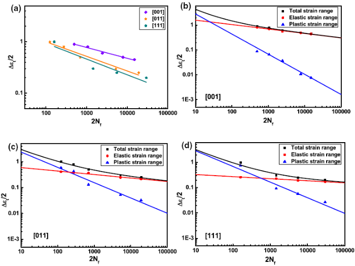
The fatigue life curves of the specimens with the [001], [011] and [111] crystal orientations at 980 °C are illustrated in Fig. 1a. It is noted that fatigue life of strain-controlled low-cycle fatigue is highly orientation dependent, and the [001] specimens show the longest fatigue life, while the [111] specimens have the shortest fatigue life. Besides, the curves of the total, elastic and plastic strain range versus the number of cycles to failure in the [001], [011] and [111] specimens are plotted in Fig. 1b-d. These curves are described by Manson-Coffin equation [22, 23] which is expressed as follows:
Δεt/2=Δεe/2+Δεp/2=($σ_{f}^{‘}$/E)(2Nf)b+$ε_{f}^{‘}$(2Nf)c, (1)
where ΔεeΔεe and ΔεpΔεp are the elastic and plastic strain ranges, respectively, NfNf is the number of cycles to failure, σ′fσf′ is fatigue strength coefficient, ε′fεf′ is the fatigue ductility coefficient, b is the fatigue strength exponent, c is the fatigue ductility exponent, and E is Young’s modulus. Under all testing strain levels, plastic deformation in the [001] specimens is far less than elastic deformation and decreases as the fatigue life increases. It is considered that the fatigue tests with the [001] orientation are dominated by elastic deformation at 980 °C. Nevertheless, the proportion of plastic deformation in the [011] and [111] specimens is much larger than that of the [001] specimens, the impact of which on fatigue tests cannot be ignored.
Fig. 1 Relationship between the fatigue life and the strain range of experimental alloy at 980 °C: a total strain range versus fatigue life of various oriented alloy, b-d total, elastic and plastic strain ranges versus the number of cycles to failure of the alloy with the [
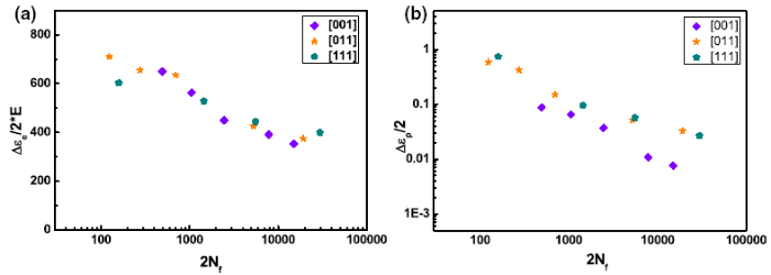
When the fatigue life is taken as a function of the modulus normalized elastic strain range by introducing elastic modulus, the difference in fatigue life among the three oriented specimens is much smaller, as shown in Fig. 2a. Thus, the orientation dependence of fatigue life is mainly determined by the elastic modulus. However, according to the function of fatigue life versus inelastic strain range (Fig. 2b), a larger inelastic strain range results in a shorter fatigue life. Additionally, a clear orientation dependence is evident on the fatigue life at 980 °C, which mainly lies between the [001] specimens and the other two oriented specimens. These results indicate an apparent distinction with previous reports on the alloys Rene N4 and DD6 [9, 13], and the amount of plastic deformation in the experimental alloy is far larger than that in the literature. Consequently, our results imply that inelastic factors also influence orientation dependence of the LCF life at 980 °C, except the impact of the material elasticity.
Fig. 2 Relationship between the fatigue life and the strain range of the experimental [
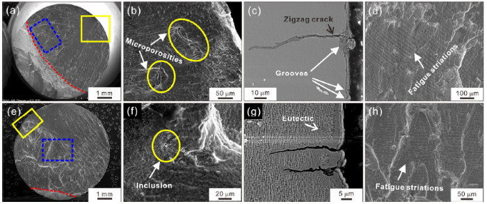
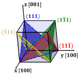
Figure 3 illustrates the fracture morphology of the [001] specimens under higher and lower strain range at 980 °C, respectively. The crack initiates from the casting microporosity or the inclusion at the specimen subsurface (Fig. 3a, e), and high magnification of the crack initiation sites is shown in Fig. 3b, f. Apart from this, the surface oxide layers near grooves and eutectics are another main crack initiation source due to serious oxidation at 980 °C, which is shown in Fig. 3c, g. Figure 4 indicates the octahedral slip planes of the [001] specimens. However, the overall appearance of the fracture surface is perpendicular to the stress axis, which indicates that the [001] specimens deform in wave slip mechanism and fracture along non-crystallographic plane at 980 °C. Apart from that, a considerable oxidation covers the surface slip so that the surface slip is barely detectable at elevated temperature. Besides, it is clearly observed in Fig. 3d, h that directional fatigue striations appear close to the fatigue step of final rupture region. When the stress at the crack tip exceeds the critical point, the final quasi-cleavage fracture rapidly breaks out. Moreover, with the increase in the strain range, the proportion of the area where the crack initiates and propagates decreases (Fig. 3a, e).
Fig. 3 SEM images of fatigue fracture of the [
Fig. 4 Schematic of the octahedral slip planes of the [
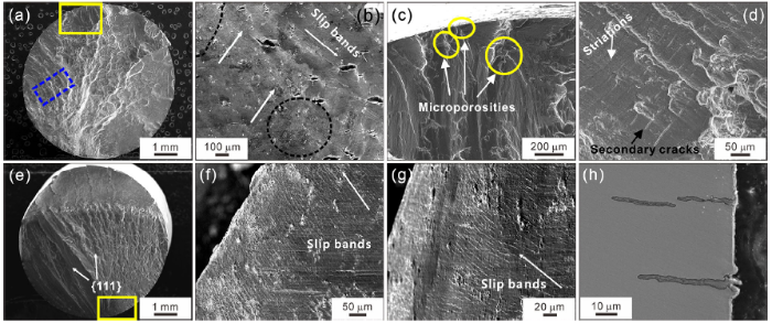
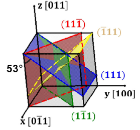
In the SEM micrograph (Fig. 5) for the [011]-oriented specimens under different strain ranges at 980 °C, the fatigue cracks originate from the microporosity or the oxide layer in the surface of the alloy (Fig. 5c, h). Compared to the [001] specimens, the fracture surfaces of the [011] specimens are uneven and consist of different small facets. The angle between the planes of the fracture surface is titled about 50° toward the loading direction; combining the schematic of the octahedral slip planes of the [011] specimens (Fig. 6), it is indicated that the crack propagates along the {111} planes ((111) and (11$\bar{1}$)). According to the surface slip morphologies in Fig. 5b, f, g, two conjugate {111} slip planes intersect with each other, and the cracks grow along the intersection line of the two {111} slip planes. Considering the fracture angle and SEM observations of the alloy with the [011] orientation, it might be deduced that the specimens fracture along the crystallography planes, and planar slip plays a significant role during the fatigue fracture. Additionally, it is clearly shown in Fig. 5d that the fatigue striations occur not far away from the crack source and the space of striations increases in the crack propagation processes, as well as many secondary cracks are evidently observed among the fatigue striations.
Fig. 5 SEM images of fatigue fracture of the [
Fig. 6 Schematic of the octahedral slip planes of the [
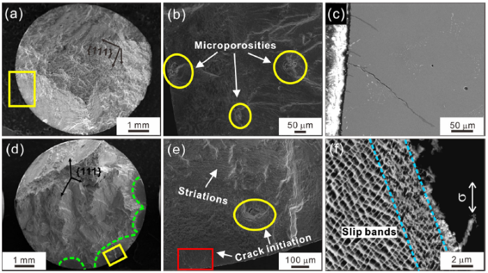
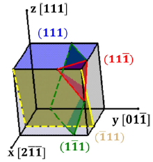
The fracture surfaces of the [111]-oriented specimens under various strain ranges at 980 °C are shown in Fig. 7. Multiple microporosities at the subsurface of the alloy promote crack initiation, the morphology indicated in yellow circular area of Fig. 7b, e. Meanwhile, the larger the number of cycles to failure is, the greater the oxidative damage of the alloy subjected to is, which results in some sites of the crack initiation being covered by the oxide layer (the areas indicated by the red box in Fig. 7e). During the cyclic loading, the surface oxide layer generates microcracks identified to propagate in a dominated slip plane (Fig. 7c). While for the strain range ∆εt/2 = 0.2%, although multiple cracks originate in several small facets perpendicular to the stress axis (the areas indicated by green dashed lines in Fig. 7d), it is noteworthy that the direction of slip bands near the fracture surface is paralleled to the fracture surface (Fig. 7f), meaning that multiple cracks spread along respective {111} slip planes. Generally, for the [111]-oriented specimens, although the (111) slip plane is perpendicular to the loading direction, the crack actually propagates along other {111} slip planes (referring to Fig. 8). The fracture surface is similar to that of the specimens with the [011] orientation but macroscopically much rougher, exhibiting the characteristic of crystallography fracture and plastic deformation mechanism of planar slip. Besides, the fatigue striations are visible near the site of the crack initiation (Fig. 7e).
Fig. 7 SEM images of fatigue fracture of the [
Fig. 8 Schematic of the octahedral slip planes of the [
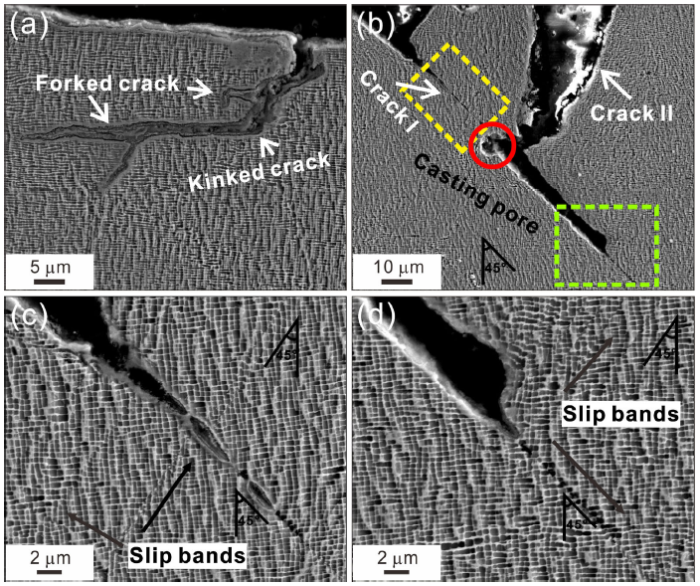
Figure 9 reveals the typical morphologies of cracks near the fracture surface on the longitudinal sections of the fatigued [001] specimens, to carry out more detailed microcosmic analysis on fatigue fracture. In Fig. 9a, the crack branch is produced by the main crack and turns toward the direction of the main crack after extending a certain distance. Previous studies [24, 25] have pointed out possible types of the crack geometry and calculated the effective stress intensity factors of the crack branch based on the stress intensity factors of the main crack. It is indicated that the crack tip is subjected to stress concentration; kinked and forked cracks can release the stress intensity and weaken the deformation around the crack tip, slowing down the crack propagation. In Fig. 9b, the secondary crack I is about 45° inclined to the loading direction, which indicates that the crack propagates on one of the octahedral slip planes, although two sets of slip traces are evident ahead of the crack tip and around the crack (Fig. 9c, d). When the cracks I and II encounter casting pores, it coalesces with the casting pores and continues to propagate along the crack I.
Fig. 9 Morphologies of secondary cracks on the longitudinal sections of the [
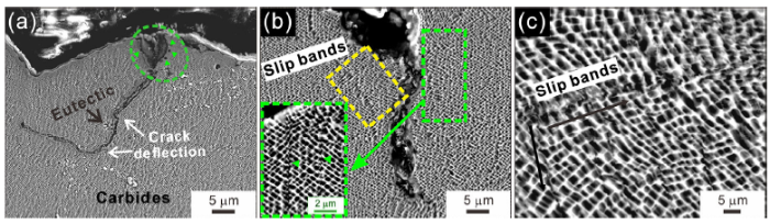
Some features of the [011]-fatigued specimens in the longitudinal sectioned microstructure are shown in Fig. 10. In Fig. 10a, near the fracture surface, secondary crack is easily generated in the interdendritic region induced by the local inhomogeneity between carbides and matrix. When the material is subjected to compressive stress at high temperature, oxides near the surface break and carbides surrounded by oxides fall off since the oxides are brittler than the matrix material, and then the exposed internal metal is re-oxidized. Subsequently, when the secondary crack encounters internal eutectics and interdendritic regions, the crack deviates from the original direction since the microstructural inhomogeneities change the stress intensity of the crack tip [24]. With respect to Fig. 10b, another kind of secondary cracks mainly extends in the (11$\bar{1}$) or (1$\bar{1}$1) plane (referring to Fig. 6). Around the secondary crack, the shearing of different slip bands causes considerable distortion in γ and γ′ phases, which weakens the strengthening of ordered γ′ phases and promotes the secondary crack propagation [26] (Fig. 10c), and the extent of shearing damage becomes weaker along the crack path.
Fig. 10 Morphologies of secondary cracks on the longitudinal sections of the [
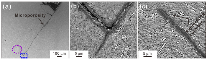
For the [111] specimens after fatigue, SEM observations of the secondary crack in the longitudinal section are shown in Fig. 11. At the junction of different slip planes, the secondary crack is easily generated and mainly propagates along single slip plane, as shown in Fig. 11a. Moreover, the crack tip connects nearby microporosities and eventually propagates parallel to the current cracking direction. Additionally, when the crack encounters carbides, the change in the propagation direction (Fig. 11b) or penetration of the carbide (Fig. 11c) depends on the local stress intensity factors at the crack tip and the strength of the carbide [3]. The carbides in Fig. 11b are large and concentrated in the lower right, resulting in local stress concentration that promotes crack growth toward the matrix. However, in Fig. 11c, fine carbides that are not completely connected have less resistance to cracking but can be easily oxidized. Under cyclic stress, the destruction of the oxide films on the surface reduces the strength of carbides and facilitates cracking through carbides [27].
Fig. 11 Morphologies of secondary cracks on the longitudinal sections of the [
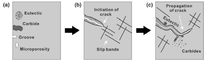
It is well known that microscopic discontinuous carbides, undissolved eutectic, oxides and defects focused on the interdendritic regions are likely to cause stress concentration, and act as the sites of fatigue crack initiation at elevated temperature [28, 29, 30]. Figure 12 shows the schematic of the crack formation and propagation. Multiple cracks generate at mocroporosities, eutectics or interdendritic carbides on the subsurface attributing to local stress concentration, and are oxidized in the subsequent deformation process. On the other hand, grooves or surface inclusions on the surface suffer much more severe oxidation damage under high temperature, resulting in the oxide layer and has an effect of wedge invasion (Fig. 12a). The crack forms at such oxidized sites owing to different thermal expansion coefficients between the oxide layer and the alloy. When subjected to cyclic loading at high temperature, fragile oxide layer on both sides of the crack falls off, and different directions of slip bands are produced at the crack tip (Fig. 12b). In the subsequent crack growth, casting pores, carbides and eutectics might alter the crack direction through changing the stress intensity factors at the crack tip, as shown in Fig. 12c. Eventually, multiple microcracks interconnect with each other until fracture, attributing to the combination of continuous oxidative damage and cyclic loading on the alloy.
Fig. 12 Schematic illustration of the crack initiation and propagation
Previous studies [31, 32, 33, 34] have pointed out that a complex interaction among the operative plastic deformation mode, the loading condition and the environment affects the fatigue life of various materials. Telesman and Ghosn [35] suggested that the fatigue fracture mode depends on oxidation effects and the stress intensity during the high-temperature LCF tests in the air. Combining the above-mentioned factors, our results show that the number of active slip planes is an influence factor on fatigue fracture for the specimens with different orientations. From the literature [36], for the FCC structures, the nominal [001] crystal direction has eight equivalent slip systems, the nominal [011] direction has four, while the nominal [111] direction has six. In the process of the specimen preparation and the LCF tests, active slip systems would change since the orientation of alloy deviates a few degrees off the nominal orientations. But beyond that a slip plane contains three slip systems; it might be that two active slip systems locate on the same plane, and hence only one active slip plane is received. For the [001] specimens, the fracture surface is relatively smooth and perpendicular to the loading direction, which might due to the fact that the specimens operate a large number of slip planes and experience sufficient thermal activation process at high temperature and the cyclic stress condition. Considering dislocation configuration of the [001] specimens reported in our previous study [21], a large number of dislocations tangle and cross-slip in the channels and form dislocation networks at γ/γ′ interfaces. The normal stress accumulated in the coplanar slip band is easily released by out-of-plane secondary slip, so that dislocations movement may be out of the slip plane though cross-slip and climbing to generate a more homogenous deformation, eventually fracture along the non-crystallographic plane [37]. With respect to the [011]- and [111]-oriented alloy, the fracture surface is uneven and consists of several {111} planes, which can conclude that the plastic deformation at the crack tip is heterogeneous on account of the small number of active slip systems. Moreover, plenty of parallel dislocation aligned in roof channels of the [011] specimens and almost no dislocation network formed in the [111] specimens reduce dislocation interactions among different slip planes [21], which promote the multiple cracks propagating along respective {111} slip planes, preferentially.
Experimental curves reveal that there is a strong orientation dependence on the LCF life, where the [001] specimens perform the longest fatigue life, while the [111] specimens the shortest. It is well known that the orientation dependence on fatigue life is mainly determined by the elastic anisotropy [9, 12]. Nevertheless, it is interesting to note that there is a difference in the curve of inelastic strain range versus the number of cycles in the three oriented specimens (Fig. 2b). Even if the total strain controlled by the [011] and [111] specimens is less than the strain of the [001] specimens, the amount of plastic deformation for the [011] and [111] specimens is far greater than the [001] specimens, while the difference between these two orientations is small (Fig. 1b-d). It is also noted that the influence of the inelastic deformation decreases as increasing the number of cycles to failure. This behavior is distinct to what has been reported earlier regarding the LCF [9, 12].
Combined with the experimental curves and the SEM observations, it can be inferred that the plasticity of materials and the number of active slip planes are also likely to be factors to influence the LCF life. According to Table 2, the plastic constants (elongation and reduction in area) of the [011] and [111] specimens are higher than the [001] specimens, meaning that specimens with these two orientations can suffer larger plastic deformation without fracture. Therefore, high plastic constants seem beneficial for the fatigue life, as indicated in Fig. 2b. However, for the [001] specimens, dislocation movement is easily extended to other slip planes through cross-slip and climbing at the elevated-temperature LCF tests. A higher number of slip planes cause larger deformation, the amount of plastic deformation in each slip band is relatively low. The specimens are mainly subjected to the elastic deformation which is beneficial for the LCF life. On the other hand, the [011] and [111] specimens fracture along crystallographic planes. Nonetheless, the main crack propagates in two dominated types of {111} slip planes for the [011] specimens during the fatigue test. With respect to the [111] specimens, although three different types of {111} slip planes occur in the fracture surface, it can be deduced from Fig. 7c that the local stress concentration at either crack initiation is primarily released along one of the {111} planes, and then multiple microcracks along different {111} planes gather together to eventually form the uneven fracture surface. Moreover, for the [011] and [111] specimens with a few active slip planes, more concentrated plastic deformation is detrimental for fatigue life. Therefore, our research reveals that the plasticity of materials and the number of active slip planes may never be ignored factors which influence the LCF life at 980 °C.
Table 2 Tensile properties of experimental alloy with different orientations at 980 °C
| Orientations | σ0.2σ0.2 (MPa) | σbσb (MPa) | Elongation (%) | Reduction in area (%) | Elastic modulus (GPa) |
|---|---|---|---|---|---|
| [001] | 792 | 850 | 23.5 | 40 | 97 |
| [011] | 575 | 620 | 29 | 46 | 175 |
| [111] | 575 | 625 | 40 | 43 | 234 |
The fracture surface and microstructures of the ruptured superalloy with the [001], [011] and [111] orientations were characterized by scanning electron microscopy at 980 °C, and the corresponding fracture behaviors have been discussed. The following conclusions can be obtained from this work:
1. The specimens with three different orientations exhibit distinct cyclic plastic deformation mechanisms on account of different active slip systems during the LCF tests at 980 °C. The wave slip causes the [001] specimens to show the non-crystallographic fracture characteristics, while the planar slip causes the [011] and [111] specimens to fracture along crystallographic planes.
2. For the superalloy with all the orientations, the sites of casting pores, eutectic, inclusion and surface oxide layer are the primary fracture crack initiators. Meanwhile, these locations inside the alloy hinder the crack propagation through changing the path of the crack growth or generating the crack branch to release the stress intensity near the crack tip.
3. At 980 °C, the elastic modulus is the strongest factor in determining the LCF life for a single-crystal superalloy. The oriented alloy with the lowest elastic modulus has the longest LCF life.
4. The number of active slip planes during fatigue deformation and the plasticity of materials also affect the LCF life, for the superalloy with different crystal orientations. For the [001] specimens, a higher number of the active slip planes promote the more dispersive deformation, which is beneficial for the LCF life. With respect to the [011] and [111] specimens, the local plastic deformation is concentrated on a few active slip planes and seems to be detrimental for the fatigue life, even though the better plasticity can resist the larger inelastic deformation compared to the [001] specimens.
Acknowledgements This work was supported by the National Natural Science Foundation of China (Nos. 51571196, 51671188 and 5160119) and Shenyang Science and Technology Project (No. 17-101-2-00). The authors are grateful for those supports.
The authors have declared that no competing interests exist.

 WeChat
/
| 〈 |
|
〉 |