Search for articles:
Yang Zhao , Wen-Ting Zhu
Corresponding authors:
Received: 2018-08-17
Revised: 2018-12-2
Online: 2019-10-10
Copyright: 2019 Editorial board of Acta Metallurgica Sinica(English Letters) Copyright reserved, Editorial board of Acta Metallurgica Sinica(English Letters)
More
Abstract
In the present study, a quenching treatment prior to two-stage heat treatment was conducted on a Fe-0.28C-1.55Mn-2.06Al transformation-induced plasticity steel to tailor the final microstructure. Compared with the microstructure of the ferrite, bainite and blocky retained austenite obtained by conventional two-stage heat treatment, the microstructure subjected to quenching plus two-stage heat treatment was composed of the ferrite, lath bainite and film-like retained austenite. The corresponding tensile behavior and mechanical stability of retained austenite were investigated by scanning electron microscopy, transmission electron microscopy and X-ray diffraction. The results show that the mechanical stability of blocky retained austenite grains is lower and most of them transform to martensite during the tensile deformation, which leads to higher ultimate tensile strength and instantaneous work hardening exponent. Film-like retained austenite has relatively higher stability, which could cause sustained work hardening and high ductility as well as product of strength and elongation.
Keywords:
In recent years, numerous studies have been focused on light-weight automobile steels for reducing CO2 emission and increasing fuel efficiency. One of the most effective methods for reducing car weight is to use advanced high strength steels in car bodies. Thus, transformation-induced plasticity (TRIP) steels have recently attracted significant interest for automotive applications due to their superior combination of high strength, ductility and crashworthiness [1, 2, 3, 4]. A typical microstructure of TRIP steel is composed of the ferrite, bainite, retained austenite and probably martensite [5, 6]. The outstanding mechanical properties of TRIP steels are closely related to multi-phase microstructure, since the TRIP effect usually arises from transformation of metastable retained austenite to martensite during the deformation [7].
C-Si-Mn steel is one of the traditional TRIP steels, and 1.5-2 wt% silicon was added, not only to suppress cementite formation during isothermal bainitic transformation, but also to enhance the volume fraction and mechanical stability of retained austenite [8]. However, high silicon content could result in a strong oxide layer forming on the surface of the steel during the hot rolling. These surface oxides are difficult to be removed by pickling, which could deteriorate the galvanizability and weldability of TRIP steels [9]. Then, many studies have shown that aluminum can inhibit the formation of cementite. Silicon was thus partially or fully replaced by aluminum in some TRIP steels [10, 11]. Besides, aluminum can accelerate the formation of bainite, which is important for the production of TRIP steels in continuous galvanizing line due to the limited processing time [2]. Moreover, the high Al content in TRIP steels leads to high carbon content of retained austenite [3], which is beneficial to the high mechanical stability of retained austenite.
In addition, the remarkable mechanical properties of TRIP steels not only depend on the fraction of retained austenite, but also on the mechanical stability of retained austenite. The mechanical stability of retained austenite is defined as its resistance to transformation under stress and strain [12]. In previous studies, the effects of carbon content [7, 13], alloying element content [14], grain size [15], grain orientation [16], morphology of retained austenite [17], microstructure [12, 18] and neighboring phases [19] on the mechanical stability of retained austenite have been investigated. For instance, the mechanical stability of retained austenite increased with increasing carbon, molybdenum and nickel contents [13, 14], or decreasing the size of retained austenite [15]. Hard surrounding phase also resulted in high mechanical stability of retained austenite [19]. But the above studies are almost related to Si-bearing TRIP steels. There are only a few studies on the mechanical stability of retained austenite in Al-containing TRIP steel [20, 21]. So the effect of retained austenite characteristics on its mechanical stability has not been clear yet. Therefore, in the present study, different microstructures of an Al-containing TRIP steel were obtained through cold rolling process followed with traditional two-step heat treatment and quenching + two-step heat treatment. And the effect of the microstructure on mechanical properties and stability of retained austenite was also discussed in details.
An Al-containing TRIP steel used for this study has the chemical composition (wt%) of C 0.28, Mn 1.55, Al 2.06, S 0.01, P 0.008 and Fe balance. The experimental steel was melted in a 25-kg vacuum induction furnace, followed by hot forging to produce a slab with a thickness of 40 mm. Subsequently, the slab was reheated to 1200 °C for 2 h and was hot rolled to a sheet of 5 mm in thickness with finishing temperature of 900 °C. Subsequent to the hot rolling, the steel sheet was cold rolled to 1 mm with a laboratory rolling mill.
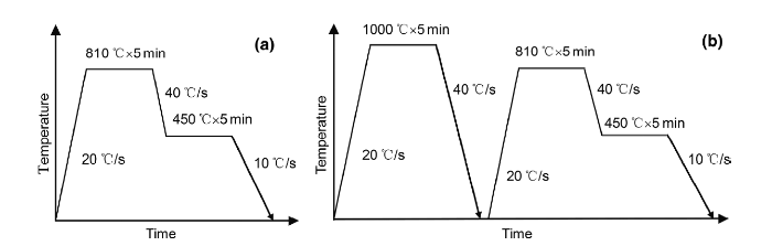
After cold rolling, the experimental steel sheets were heat treated by two processes, which are classified as processes A and B, respectively, as shown in Fig. 1. Both the heat treatment processes were conducted on a continuous annealing simulator. Process A is a typical two-step heat treatment, which employs an isothermal bainitic transformation after intercritical annealing and produces equiaxed ferrite grains surrounded by bainite and retained austenite [22]. Ac1 and Ac3 temperatures of the experimental steel were determined to be 700 °C and 920 °C by thermal dilatometer, respectively. Thus, the intercritical annealing temperature in process A was determined to be (Ac1 + Ac3)/2 = 810 °C to obtain equal fractions of austenite and ferrite. Process B is a three-step heat treatment based on process A, which can produce ferrite, and lath bainite surrounded by lath retained austenite. The steel sheets heat treated by processes A and B are named as samples A and B, respectively.
Fig. 1 Schematic diagram of heat treatments: a Process A; b Process B
The microstructures of samples A and B were observed using a scanning electron microscope (SEM, ZEISS ULTRA 55) equipped with electron backscatter diffraction (EBSD) system. The SEM specimens were polished and etched by a 4 vol% nital solution. The microstructures were also characterized by a transmission electron microscope (TEM, FEI TECNAI G2 F20). EBSD was employed to determine the distribution, morphology and size of retained austenite. The tests with a step size of 0.05 μm were conducted on the RD-ND plane (RD: rolling direction, ND: normal direction). After mechanical polishing, the EBSD specimens were electropolished using a solution of 12.5 vol% perchloric acid and 87.5 vol% absolute ethyl alcohol. HKL-channel 5 software was used for data acquisition and post-processing.
The tensile specimens with gauge length of 50 mm and width of 12.5 mm were machined from the heat-treated steel sheets with the tensile axis paralleled to the rolling direction. Tensile tests were carried out at room temperature with a crosshead speed of 3 mm/min on a CMT5105 tensile testing machine. And the interrupted tensile tests were also performed to study the mechanical stability of retained austenite.
The volume fraction of retained austenite was measured by X-ray diffraction (XRD) with Cu-Kα. The surface of specimens was mechanically polished by 1500# abrasive paper and subsequently electropolished with perchloric acid solution. The volume fraction of retained austenite was quantified by analyzing the integrated intensities of (200), (220) and (311) austenite peaks as well as (200) and (211) ferrite peaks. The volume fraction of retained austenite was calculated by the following equation [23].
Vγ=1.4Iγ/(Iα+1.4Iγ),(1)
where Vγ is the volume fraction of retained austenite, Iγ and Iα are the average integrated intensities of austenite and ferrite peaks, respectively.
In addition, the carbon content of retained austenite was calculated by substituting the lattice parameter (αγ) measured from (220) austenite peak into the following equation [24].
Cγ=(αγ-3.5467)/0.0467.(2)
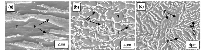
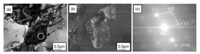
Figure 2 shows SEM micrographs of cold-rolled sample, samples A and B. From Fig. 2a, it can be seen that the microstructure of cold-rolled sample consists ferrite (F) and pearlite (P). Pearlite was transformed to austenite during intercritical annealing process, a certain fraction austenite was transformed to bainite during isothermal bainitic transformation process, and finally some austenite was retained after cooling to the room temperature [3]. The microstructure of sample A was composed of polygonal ferrite (PF), bainite (B) and retained austenite (RA), as shown in Fig. 2b. Furthermore, most of the retained austenite in sample A shows blocky morphology and locates along the ferrite grain boundaries, as shown in Fig. 3a, b. The selected area electron diffraction pattern (SAEDP) of the circled area (as shown in Fig. 3c) confirmed the existence of blocky retained austenite. The size of blocky retained austenite is about 0.5-2 μm.
Fig. 2 SEM micrographs of experimental steel treated by different heat treatment processes: a cold-rolled sample; b sample A; c sample B
Fig. 3 Representative TEM images of blocky retained austenite in sample A: a bright field image; b dark field image; c SAEDP of blocky retained austenite in circled area in a
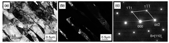
As shown in Fig. 2c, the microstructure of sample B comprises ferrite, lath bainite (LB) and film-like retained austenite. The SAEDP reveals the existence of film-like retained austenite, as shown in Fig. 4c. The film-like retained austenite is adjacent to the lath bainite in sample B. The width of film-like retained austenite is less than 0.5 μm, while the length is more than 3 μm. Combined with XRD results, the volume fractions of retained austenite in samples A and B are calculated to be 12.98% and 6.61%, respectively. The carbon contents of retained austenite in samples A and B are determined to be 1.45% and 1.59%, respectively. That is to say, the carbon content of film-like retained austenite is higher than that of blocky retained austenite. By using energy dispersive X-ray spectroscopy analysis, the Mn and Al contents in retained austenite were measured, and the final content was the average value of five measurements. The Mn contents of blocky and film-like retained austenite are 1.72% and 1.76%, respectively, which are larger than nominal Mn content. The Mn partitioning during intercritical annealing is responsible for the higher Mn content of retained austenite. Meanwhile, the Al contents of blocky and film-like retained austenite are 1.67% and 1.61%, respectively. There are small differences in Mn and Al contents between blocky and film-like retained austenite due to the short holding time, so their effects on mechanical stability of two kinds of retained austenite can be neglected.
Fig. 4 Representative TEM images of film-like retained austenite in sample B: a bright field image; b dark field image; c SAEDP of film-like retained austenite in circled area in a
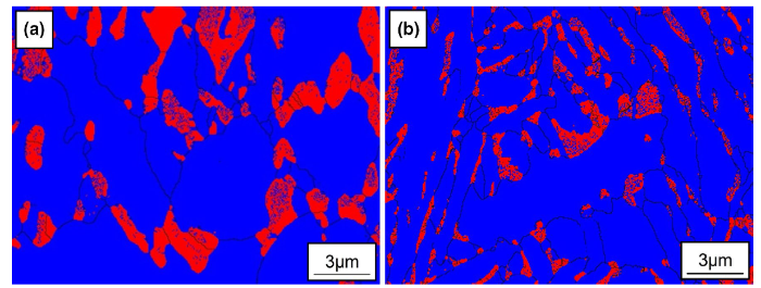
Figure 5 presents the distribution, morphology and size of retained austenite in samples A and B. The red colored regions represent retained austenite, while the blue ones represent ferrite or bainite. From Fig. 5, the different morphologies of retained austenite can be readily observed. In sample A, retained austenite is blocky, while that one in sample B is film-like. Almost all of retained austenite located along the ferrite or bainite grain boundaries regardless of its morphology.
Fig. 5 EBSD maps of retained austenite in as-heat-treated samples: a sample A; b sample B
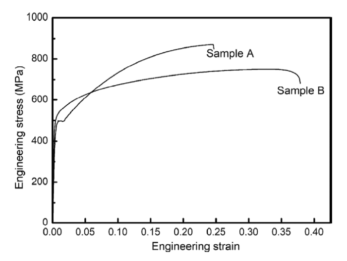
The engineering stress-strain curves of samples A and B at room temperature are presented in Fig. 6, and their tensile properties are summarized in Table 1. A discontinuous yield plateau is obvious in the curve of sample A, whereas continuous yielding displays in sample B. It has been studied that discontinuous yielding is related to the low mobile dislocation density [25]. And the yield plateau can be eliminated by temper rolling after heat treatment process.
Fig. 6 Engineering stress-strain curves of samples A and B at room temperature
Table 1 Tensile properties of samples A and B at room temperature
| Sample | YS (MPa) | UTS (MPa) | El (%) | UTS × El (GPa %) |
|---|---|---|---|---|
| A | 489 | 873 | 26.7 | 23.3 |
| B | 538 | 764 | 33.3 | 25.4 |
The ultimate tensile strength (UTS) of sample B is lower, compared to that of sample A, but the yield strength (YS), elongation (El) as well as product of strength and elongation (UTS × El) are higher. The similar results have been reported by Chiang et al. [26] and Sugimoto et al. [27], and the larger elongation can be attributed to the sustained work hardening in a large strain range in sample B, which will be discussed below.
The work hardening behavior could be characterized by instantaneous work hardening exponent (ninst). The ninst can be calculated from the following equation [26].
ninst=d(lnσ)/d(lnε),(3)
where σ is the true stress and ε is the true strain.
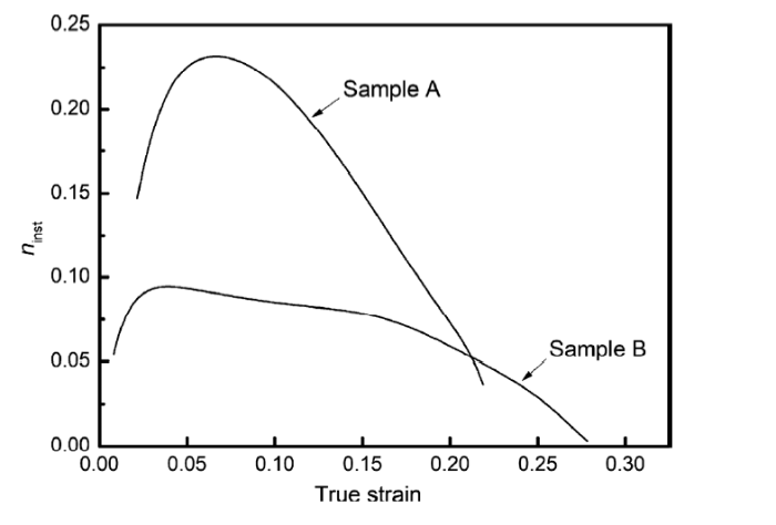
The ninst has been widely used as a parameter of formability in sheet materials [26, 28], where sheet formability increases with increase in ninst. Figure 7 shows ninst values of samples A and B as a function of true strain. ninst of sample A is higher than that of sample B, when the true strain is less than 0.2. ninst of sample A increases steeply in the initial stage of deformation and achieves a maximum value at the strain of 0.07, and then decreases gradually until the necking point. Sample B exhibits a flatter, more sustained work hardening behavior up to the necking point. Therefore, film-like retained austenite can bring about sustained work hardening in TRIP steels.
Fig. 7 Variation in nisnt values with true strain of samples A and B
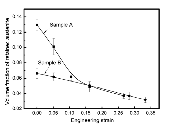
Figure 8 shows the volume fractions of retained austenite in samples A and B as a function of engineering strain. The volume fractions of retained austenite of both samples decrease gradually with an increase in strain due to the continuous transformation of retained austenite to martensite. It can be seen that a large amount of retained austenite of sample A has transformed to martensite during the early stage of deformation. Given that ninst of sample A increases quickly at the initial stage of tensile deformation, it can be concluded that the sharp increase in ninst to the maximum can be attributed to the rapid transformation of retained austenite.
Fig. 8 Relationship between volume fraction of retained austenite and engineering strain
The percentage of transformed blocky retained austenite in sample A after fracture is about 71.2%. The high value of UTS of sample A arises from the high volume fraction of retained austenite which could eventually transform to martensite, while only about 51.8% film-like retained austenite in sample B transforms to martensite until fracture. A large amount of film-like retained austenite in sample B is still present after fracture due to the high mechanical stability. The contribution of film-like retained austenite to strain hardening and UTS is less than the blocky one. It can be concluded that blocky retained austenite leads to more TRIP effect during deformation.
The mechanical stability of retained austenite against strain-induced transformation can be evaluated by a constant k, which is determined by the following equation [27].
logfγ=logfγ0-kε,(4)
where fγ0 and fγ represent an initial volume fraction of retained austenite and untransformed retained austenite content after straining to strain ε, respectively. A low k corresponds to high mechanical stability of retained austenite.
Using least-square method, the k of samples A and B is determined to be 2.09 and 0.95, respectively. It is obvious that sample B has lower value of k. In other words, film-like retained austenite is more stable during the tensile deformation than blocky one. The slow transformation rate from metastable austenite to martensite in sample B allows sustained strain hardening during the deformation. That is to say, TRIP steel with film-like retained austenite has high ductility. Chen et al. [29] have also revealed that film-like retained austenite possesses relatively higher mechanical stability, but its contribution to strain hardening and UTS is less than that of blocky one.
The difference in mechanical stability between blocky and film-like retained austenite can be ascribed to the different carbon content and their neighboring phases. In term of carbon content, the higher carbon contents of film-like retained austenite increase the strength or shear resistance for the onset of shear transformation of metastable austenite [15]. Thus, greater driving force is required for the transformation of film-like retained austenite. A lot of studies have also suggested that retained austenite with higher carbon content has higher mechanical stability [30, 31, 32]. As mentioned above, the film-like retained austenite is surrounded by hard lath bainite. It is revealed that the hard phase surrounding retained austenite would inhibit the martensite transformation of retained austenite by generating high hydrostatic pressure, which prevents the volume expansion and shear deformation [18, 33, 34]. In summary, the higher mechanical stability of film-like retained austenite arises from higher carbon content and hydrostatic pressure from neighboring hard lath bainite.
The morphology of retained austenite is associated with its chemical composition and surrounding phase. It has been demonstrated that the film-like retained austenite usually has higher carbon content and is surrounded by the hard phase regardless of the chemical composition of TRIP steel [12, 26, 27]. The film-like retained austenite in Si-containing TRIP steel should have a higher mechanical stability than the blocky one, and this was confirmed by previous studies [12, 27]. Compared with Si, Al has better stabilization effect of retained austenite, and the retained austenite in Al-containing TRIP steel thus has higher mechanical stability than the one in Si-containing TRIP steel at an equivalent content of Al or Si [16, 35, 36]. Compared with Si, Al can result in higher carbon content of retained austenite, and this is the reason why retained austenite in Al-containing TRIP steel has the higher mechanical stability [35].
For designing TRIP steels with high elongation as well as product of strength and elongation, film-like retained austenite is preferred. The chemical compositions and heat treatment processes of TRIP steels should be modified to achieve more film-like retained austenite.
By controlling the microstructure prior to heat treatment, two final microstructures with different morphologies of retained austenite in an Al-containing TRIP steel were obtained. One microstructure consists of polygonal ferrite, bainite and blocky retained austenite, and the other is a mixture of ferrite, lath bainite and film-like retained austenite. Their tensile properties and mechanical stability of retained austenite were investigated. Conclusions are drawn as follows.
1.Compared to the TRIP steel with mixed ferrite, lath bainite and film-like retained austenite, the one with polygonal ferrite, bainite and blocky retained austenite has higher ultimate tensile strength, but lower yield strength, elongation as well as product of strength and elongation.
2.Blocky retained austenite contributes to high instantaneous work hardening exponent and ultimate tensile strength due to higher transformation rate of metastable austenite to martensite during tensile deformation.
3.The mechanical stability of film-like retained austenite is higher than that of blocky one. The higher carbon content of retained austenite and hydrostatic pressure from neighboring lath bainite are responsible for the higher mechanical stability.
This work was financially supported by the National Natural Science Foundation of China (No. 51501031) and the Natural Science Foundation of Liaoning Province (No. 20170520348).

 WeChat
/
| 〈 |
|
〉 |