Search for articles:
Pei-Jiang Liu , Vincent Ming Hong Ng
Corresponding authors:
Received: 2017-06-21
Revised: 2017-06-21
Online: 2018-02-20
Copyright: 2018 Editorial board of Acta Metallurgica Sinica(English Letters) Copyright reserved, Editorial board of Acta Metallurgica Sinica(English Letters)
More
Abstract
Microwave absorption properties of spherical NiO particles and Co0.2Ni0.4Zn0.4Fe2O4 (CNZF) ferrites with single-layer and double-layer absorbers were studied in the frequency range of 2-18 GHz. The spherical NiO particles were synthesized by using a hydrothermal process, while the CNZF powders were prepared by using a sol-gel autoignition method. The double-layer absorbers, composed of 30 wt% NiO as matching layer and 30 wt% CNZF as absorption layer, with a total thickness of 3.2 mm, exhibited a maximum reflection loss (RL) of -67.0 dB at 9.2 GHz and an effective absorbing bandwidth below -10 dB to be 3.9 GHz from 7.0 to 10.9 GHz. The excellent microwave absorption performance of the double-layer absorbers should be ascribed to the high impedance matching ratio, the great microwave attenuation capability, and well-coupled layer.
Keywords:
With the continuous development of electronic technology, especially the rapid advance of novel broadband and high-power electronic devices, such as ultra-wide-band radar, communication satellite, and precision-guided system, high-performance microwave absorption materials with large absorption capability and wide absorption bandwidth are strongly demanded to eliminate unfavorable electromagnetic (EM) waves [1, 2, 3, 4, 5]. Searching for high-performance microwave absorption materials is still a great challenge. Among various microwave absorption materials, the ferrites have grabbed considerable attention for EM wave attenuation, owing to their high magnetic loss, large Snoek’s limit, and abundant natural resource [6, 7]. For example, Li-Zn/La ferrite hollow microspheres showed enhanced absorption performance with a minimum reflection loss (RL) value of -30.2 dB and an effective frequency bandwidth covering 4.7-7.7 GHz [8]. Till now, spinel ferrites, like Li-Zn, Mn-Zn, and Ni-Zn ferrites, have been proved to be promising candidates as microwave absorption materials because of their unique magnetic properties and chemical stabilities [9, 10]. However, the ferrites suffer from large density, poor flexibility, interfacial impedance mismatching, and limited loss mechanism [11, 12]. Therefore, introduction of other lossy materials has become an imperative solution to boost the microwave absorption performance of the ferrites [13, 14, 15].
Nickel oxide (NiO) with NaCl-style structure has been extensively explored for the applications in gas sensors, solar cells, catalysts, semiconductors, and magnetic materials, due to its low conductivity, high hole mobility, low cost, and environmentally friendly [16, 17, 18, 19], although NiO is not among the traditional absorption material due to its poor response in the microwave range. However, with the molecular structure varying, metallic oxide can be turned from this inactive state into an exciting absorption material with an innovative collective movement of interfacial dipole mechanism [20]. For example, NiO nanorings on SiC, a novel hierarchical structure, showed an enhanced RL value exceeding -40.0 dB, with a broad bandwidth covering 85% of X-band [21]. Among various available structures, hierarchical spherical structures have caught great attention, owing to their broad internal contact area, large number of grain boundaries, and high specific surface area, which all could have a significant contribution to dielectric loss [22]. More importantly, the weight of spherical structures is much lower than those of other solid structures. In view of that, constructing and assembling hierarchical spherical NiO is of utmost importance [23, 24].
More recently, microwave absorption materials with double-layer structures have been shown to exhibit enhanced high-performance, since the absorption ability and response bandwidth of sing-layer absorbers are hard to meet the requirements of next-generation microwave absorption materials [25, 26, 27]. Das et al. [28] reported microwave absorption properties of double-layer composites based on Co-Zn ferrite and TiO2, revealing that the reflection loss value could reach -24.3 dB at 12.02 GHz. Ren et al. [26] investigated absorbing properties of carbonyl iron/barium hexaferrite double-layer composites, which exhibited a minimum reflection loss of -55.4 dB, along with an effective bandwidth of 5.2 GHz. However, up to now, the microwave attenuation mechanism of double-layer absorbers has not been clarified. In present study, we reported double-layer microwave absorbers based on spinel ferrite Co0.2Ni0.4Zn0.4Fe2O4 (CNZF) and spherical NiO composites. Morphology, electromagnetic, and microwave absorption properties of the double-layer microwave absorbers were studied in detail and made a comparison with the single-layer ones. Moreover, impedance matching characteristics and attenuation constant of the matching layer have also been systematically discussed.
All materials and reagents used in this study were commercially purchased from Aladdin Chemical Reagent, China, and used as received without further purification. DI water was prepared in our laboratory and used to all experiments.
Co0.2Ni0.4Zn0.4Fe2O4 (CNZF) ferrite powder was synthesized by using a sol-gel and autoignition method. Firstly, metallic nitrates with a molar ratio of Co2+/Ni2+/Zn2+/Fe3+ to be 0.2:0.4:0.4:2 and citric acid were added in 60 mL DI water with continuously stirring. After forming a clean solution, ammonia was dropwise added to adjust the pH to be 6. Subsequently, the obtained dark solution was heated to 80 °C under stirring for another 6 h. After that, the dark gels were dried at 200 °C in an air oven. Finally, the powder was calcinated at 1080 °C, and the target CNZF ferrite was obtained by slowly cooling to room temperature and grinded in an agate mortar.
To synthesis spherical NiO particle, 1.20 g Ni(NO3)2·6H2O, 0.47 g NaCl, and 5.25 g NaAc were dissolved in 40 mL ethylene glycol, followed by ultrasonication for 0.5 h. After the mixture color became green, the solution was transferred to a Teflon-lined stainless autoclave with a volume of 50 mL. Then, the autoclave was kept at 190 °C for 8 h. After cooling down to room temperature, the green slurry was filtered and thoroughly washed with DI water, followed by drying at 60 °C in vacuum. Finally, spherical NiO particles were obtained after being calcined at 300 °C for 2 h in air.
For electromagnetic parameter measurement, composites were synthesized by mixing the NiO and CNZF separately with paraffin, with a weight percentage of 30 wt% each. The paraffin mixtures were hot pressed to form toroidal samples with a 3.04 mm inner diameter, 7.00 mm outer diameter, and 2.00 mm thickness. Composites for electromagnetic measurement are labeled as CNZF and NiO hereafter.
Crystalline structures of NiO and CNZF were examined by using a Bruker D8 DISCOVER X-ray diffractometer with Cu Kα radiation (λ = 0.15406 nm) at an accelerated voltage of 40 kV. Fourier transform infrared spectroscopy (FT-IR) of the samples was analyzed by using a Bruker Vector 33 in the range of 4000-500 cm-1. Structures and morphologies of the samples were observed by using scanning electron microscopy (SEM, Hitachi S-4800N) and transmission electron microscopy (TEM, Tecnai 12 microscope). Electromagnetic parameters of the composites were measured by using a vector network analyzer (Agilent PNA N5224A) over 2-18 GHz with the coaxial line method. The samples were inserted into a copper holder and connected between the waveguide flanges of the instrument. Reflection losses of the single- and double-layer absorbers were calculated according to the measured complex permittivity and permeability parameter data.
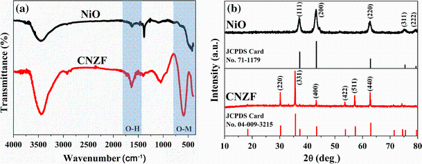
Figure 1a shows FT-IR spectra of the as-synthesized samples. For both NiO and CNZF, the band located at 1600 cm-1 is related to the bending vibration of O-H bond of the absorbed water. Compared with CNZF, NiO sample shows lower intensity at 1600 cm-1, indicating that the absorbed water molecules are easily removed due to its hierarchical spherical structure. The characteristic bands over 400-700 cm-1 are originated from the lattice stretching vibrations related to the cations and oxygen ions, proving the formation of oxides of NiO and CNZF [29]. Figure 1b exhibits X-ray diffraction (XRD) patterns of the NiO and CNZF samples. As illustrated, five distinct characteristic peaks labeled in the curve of NiO corresponding to the crystallographic planes of (111), (200), (220), (311), and (222) are in a good agreement with those of the standard cubic NiO (JCPDS No. 71-1179). As for CNZF, the XRD pattern has major peaks related to the (220), (331), (400), (422), (511), and (440) planes, matching well with the reference data of JCPDS No. 04-009-3215 for typical spinel ferrite. Comparatively, diffraction peaks of CNZF are much sharper than those of NiO, implying that CNZF has a high crystallization nature.
Fig. 1 a FT-IR spectra, b XRD patterns of NiO and CNZF
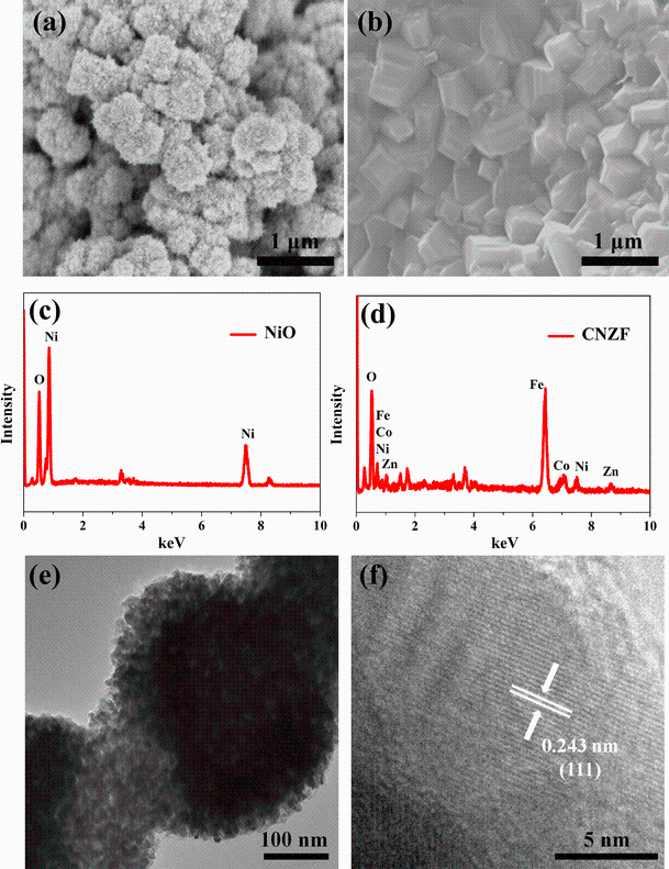
Representative SEM images of the NiO and CNZF powders are shown in Fig. 2. As shown in Fig. 2a, the NiO sample consists of particles with a hierarchical sphere-like morphology, with a relatively narrow size distribution of 200-350 nm. Meanwhile, the spherical particles possess a relatively rough surface, because they are assembled from numerous nanosized NiO particles. In case of CNZF, the magnetic particles show a typical cubic geometrical structure, with an abroad diameter size of 100-500 nm (Fig. 2b). In addition, the CNZF particles are polydisperse showing a trend of aggregate, because of their high surface energy and strong magnetic force [30]. EDS mappings of the two samples are shown in Fig. 2c, d, confirming the composition of the two oxides. TEM and HRTEM images of the NiO particles are shown in Fig. 2e, f, confirming that the spherical particles are composed of a plenty of NiO nanoparticles, with diameters of 15-25 nm. The lattice spacing of 0.243 nm is observed, which corresponds to the d spacing of the (111) crystallographic planes of NiO particles (Fig. 2f). It is necessary to mention that a small amount of amorphous carbon is observed with the NiO particles, implying that the by-product of ethylene glycol was not completely removed during calcination process.
Fig. 2 SEM images of a NiO, b CNZF, EDS spectra of c NiO, d CNZF, e TEM, f HRTEM of NiO sample
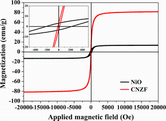
Magnetic properties of the NiO and CNZF particles were tested by using a vibrating sample magnetometer at room temperature (Fig. 3). The NiO has a relatively low saturation magnetization (Ms) value of 13.4 emu/g, coupled with a relatively large coercivity (Hc) value of 223 Oe (the inset of Fig. 3). It is well established that the magnetism of the NiO particle is attributed to the broken bonds and lattice distortion in the hierarchical spherical structure [31]. For CNZF, the value of Ms is as large as 84.1 emu/g. Meanwhile, the Hc value is as low as 13 Oe, exhibiting typical soft ferromagnetic behavior [32].
Fig. 3 Magnetic hysteresis loops of NiO and CNZF powders
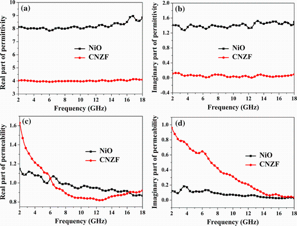
In general, microwave absorption properties of materials are determined by the complex relative permittivity (εr = ε′ - jε″) and permeability (μr = μ′ - jμ″), as well as the impedance matching characteristics and structures. Complex relative permittivity and permeability of the wax-based composite samples are shown in Fig. 4. For NiO, the values of ε′ and ε″ are in the ranges of 7.8-9.0 and 1.3-1.5, respectively, both of which are moderate in terms of impedance matching characteristic. For CNZF, the values of ε′ and ε″ have a fluctuation at around 4.0 and 0.1, respectively. It is notably that the ε′ and ε″ values of the NiO composite are larger than those of the CNZF one. Generally, the real part (ε′) and imaginary part (ε″) are related to storage capability and dissipation of the electromagnetic (EM) energy in the absorbers at the alternating EM fields [33]. High values of ε′ and ε″ imply high storage and loss capacity of the microwave energy, which depends on the multiple polarization stemming from the heterogeneous structures of the spherical NiO particles. Thanks to the complicated hierarchical structures and nanosized scale, numerous NiO-NiO interfaces and junctions are formed in the spherical particles, which leads to bound charges accumulation at the interfaces and junctions, thus having the interfacial polarization as well as corresponding relaxation [34]. In addition, the clustered defects on surfaces of the NiO particles originating from oxygen vacancies could bring out uneven charge distribution, resulting in additional dipole polarization [35, 36].
Fig. 4 Frequency dependent on relative complex permittivities a, b, relative complex permeabilities c, d of the NiO and CNZF composites
Real (μ′) and imaginary (μ″) parts of the complex permeability of as-obtained samples are shown in Fig. 4. For μ′, NiO sample exhibits a decline trend from 1.1 to 0.9 over the whole frequency region (Fig. 4c). At the same time, μ′ values of the CNZF sample first decrease from 1.6 to 0.8 up to 12 GHz and then slightly increase to 0.9 as frequency in increased from 12 to 18 GHz. For NiO, the μ″ values keep nearly constant at about 0.1 with a very small fluctuation over the whole frequency range, whereas those of the CNZF sample rapidly decrease from 0.9 to nearly 0. Apparently, the CNZF composite possesses a greater μ″ value than the NiO one, especially in the low frequency region, because the former is a soft magnetic ferrite [37]. Generally, magnetic loss could be stemmed from natural resonance, exchange resonance, hysteresis loss, domain wall motion, and eddy current effect [29]. Since the hysteresis loss is proportional to the area of hysteresis loop, it can be excluded in present paper [29]. Meanwhile, the magnetic loss may be not originated from the domain wall resonance, which often happens at megahertz frequency region. According to our previous work, the eddy current effect can also be ruled out, as the eddy current coefficient varies with increasing frequency [13]. Thus, the enhanced μ″ of CNZF could be attributed to the multiple resonance, including natural resonance and exchange resonance [38]. According to Liu’s work [39], the exchange resonance usually occurs at a higher frequency than the natural resonance. Hence, we conclude that the peaks of two samples below 8.0 GHz should be ascribed to the natural resonance, while other peaks at a higher frequency region correspond to the exchange resonance.
Microwave absorption properties of single-layer and double-layer absorbers are characterized with reflection loss (RL), which is calculated by using the following equations [29, 40, 41, 42],
$R_{\text{L}} (\text{dB}) = 20\log |(Z_{{\text{in}}} - Z_{0} )/(Z_{{\text{in}}} + Z_{0} )|,$ (1)
$Z_{{\text{in}}} = Z_{0} \sqrt {\mu_{\text{r}} \text{/}\varepsilon_{\text{r}} } \text{tanh}\left[ {j\left( {\text{2}\pi fd\text{/}c} \right)\sqrt {\varepsilon_{\text{r}} \mu_{\text{r}} } } \right],$ (2)
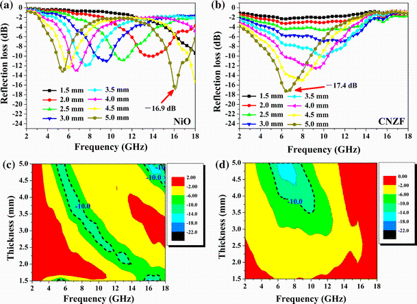
where Zin is the input impedance of the absorber, Z0 is the impedance of free space (377 Ω), f is the frequency of microwave, d is the absorber thickness, and c is the velocity of light in free space. Generally speaking, RL value of -10 dB is equivalent to 90% attenuation of the incident microwave, which is usually regarded as a benchmark to evaluation absorbers in practical applications. RL values of the single-layer absorbers based on the NiO and CNZF composites over 2-18 GHz with different thicknesses are illustrated in Fig. 5a, b. Both samples exhibit weak microwave absorption capability. The NiO sample only shows a maximum RL value of -16.9 dB at 16.1 GHz with a thickness of 5.0 mm, coupled with an absorbing bandwidth below -10 dB to be as wide as 1.9 GHz (Fig. 5a), while the CNZF sample shows a maximum RL value of -17.4 dB at 6.6 GHz, together with an effective bandwidth to be 3.8 GHz (Fig. 5b). The poor microwave absorption capability could be ascribed to their simple absorption mechanism. In addition, the optimal RL peaks of the two samples have a trend to shift toward the lower frequencies as the absorber thickness is increased from 1.5 to 5.0 mm. This phenomenon can be explained by the 1/4 wavelength cancelation equation [43], which is given by:
Fig. 5 Reflection loss curves of the single-layer absorbers of a NiO, b CNZF, together 2D contour maps of the reflection loss of c NiO, d CNZF
$t_{\text{m}} = n\lambda /4 = nc/4f_{\text{m}} (\varepsilon_{\text{r}} \mu_{\text{r}} )^{1/2} ,$ (3)
where tm and fm are the corresponding thickness and frequency of the maximum RL peaks, respectively. Obviously, the thickness of the absorber is inversely proportional to the frequency of peak positions. Effective bandwidth usually means the frequency region in which RL value is less than -10 dB. It is another vital factor to evaluate the microwave absorption performance. To compare absorbing effective bandwidth, RL values of the NiO and CNZF samples have been described with the contour maps, as shown in Fig. 5c, d. Under a specified absorber thickness, the CNZF sample shows a broader effective bandwidth than the NiO one, which is highlighted by the black imaginary line. However, the CNZF sample only has microwave absorption ability in lower frequency range from 4.9 to 10.4 GHz, with relatively large thicknesses, while NiO shows a broader absorbing bandwidth almost covering frequency range from 4.9 to 18 GHz.
Obviously, the two single-layer absorbers are still unable to satisfy the requirements of advanced absorbing materials. Therefore, double-layer absorbers are proposed, due to their high absorbing capability, wide effective bandwidth, and small thickness. For a double-layer microwave absorber, its Zin can be calculated according to the following equation [44]:
$Z_{{\text{in}}} = \frac{{\sqrt {\frac{{\mu_{2} }}{{\varepsilon_{2} }}\left( {\sqrt {\frac{{\mu_{1} }}{{\varepsilon_{1} }}} \tanh \left[ {j\left( {\frac{{2\pi fd_{1} }}{c}} \right)\sqrt {\mu_{1} \varepsilon_{1} } } \right] + \sqrt {\frac{{\mu_{2} }}{{\varepsilon_{2} }}\tanh \left[ {j\left( {\frac{{2\pi fd_{2} }}{c}} \right)\sqrt {\mu_{2} \varepsilon_{2} } } \right]} } \right)} }}{{\sqrt {\frac{{\mu_{2} }}{{\varepsilon_{2} }} + \sqrt {\frac{{\mu_{1} }}{{\varepsilon_{1} }}} \tanh \left[ {j\left( {\frac{{2\pi fd_{1} }}{c}} \right)\sqrt {\mu_{1} \varepsilon_{1} } } \right]} \tanh \left[ {j\left( {\frac{{2\pi fd_{2} }}{c}} \right)\sqrt {\mu_{2} \varepsilon_{2} } } \right]}},$ (4)
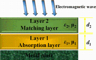
where d1, d2, ε1, ε2, μ1, and μ2 are the thicknesses, relative complex permittivity, and complex permeability of Layers 1 and 2, respectively. c and f are the similar parameters in Eq. (2). The geometry schematic of a double-layer absorber with a metal plate is illustrated in Fig. 6. Layer 1 refers to the absorption layer, while Layer 2 refers to the matching layer. When the incident EM wave irradiates the absorber surface, it can penetrate the matching layer without minimized reflection and will be consumed in the absorption layer [25].
Fig. 6 Schematic diagram of the double-layer absorber supported by a metal plate
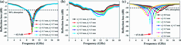
RL properties of the double-layer microwave absorber consisting of CNZF composite as the absorption layer and the NiO one as the matching layer, with a total thickness of 3.0 mm, are presented in Fig. 7a. As the thickness of the CNZF absorption layer is 1.3 mm and that of the NiO matching layer is 1.7 mm, the absorber shows a maximum RL value of -42.5 dB. With the optimized thicknesses, the efficient bandwidth (less than -10 dB) covers a frequency range from 7.8 to 11.3 GHz. Compared with the CNZF and NiO single-layer absorbers (d = 5 mm, as shown in Fig. 5), both the absorption capability and effective bandwidth are significantly enhanced for the double-layer structure, while the thickness is reduced. For comparison, RL values of the double-layer absorber with NiO absorption layer and CNZF matching layer filled are also examined. As shown in Fig. 7b, the absorber shows a poor microwave absorption property, with the maximum RL values to be less than -8 dB over the measurement frequency range. The poor microwave absorption performance should be originated from the uncoupled combination of the two layers.
Fig. 7 a Reflection loss curves of the double-layer absorbers consisting of matching layer (NiO) and absorption layer (CNZF). b Reflection loss curves of the double-layer absorbers consisting of matching layer (CNZF) and absorption layer (NiO). c Reflection loss curves of the double-layer absorbers consisting of the fixed matching layer thickness (1.7 mm) filled with NiO and varied absorption layer thicknesses from 0.9 to 2.1 mm filled with CNZF
Figure 7c exhibits RL curves of the double-layer absorber, with thicknesses of the CNZF absorption layer varied from 0.9 to 2.1 mm and the coupled NiO matching fixed to be 1.7 mm. As the absorption layer thickness is 1.5 mm, the absorber has a maximum RL value of -67.0 dB at 9.2 GHz, with an absorption bandwidth covering 3.9 GHz, from 7.0 to 10.9 GHz. As the absorption layer thickness is increased from 0.9 to 2.1 mm, the RL values below -10 dB present a broad frequency range of 5.5-13.4 GHz, offering a flexibility to design double-layer absorbers with desired absorption ranges. Table 1 lists the microwave absorption performance of some recently reported double-layer absorbers [45, 46, 47, 48, 49]. Comparatively, our double-layer absorbers have stronger absorption capability, broader effective bandwidth, and thinner layer thickness.
Table 1 Reported microwave absorption properties of recent some double-layer absorbers
| Absorption layer | Matching layer | Absorption layer thickness (mm) | Total thickness (mm) | Minimum RL value (dB) | Bandwidth RL < -10 dB (GHz) | References |
|---|---|---|---|---|---|---|
| 50 wt% carbon black powder | 50 wt% carbonyl iron powder | 2.0 | 4.0 | -10.0 | 3.2 | [45] |
| 60 wt% BaCo2Fe16O27 powder | 60 wt% BaFe12O19 and short carbon fiber | 1.0 | 2.0 | -22.0 | 3.2 | [46] |
| 30 wt% Mn-Zn ferrite powder | 10 wt% silica fume powder | 20.0 | 30.0 | -15.0 | 4.6 | [47] |
| 5.2 wt% La-doped MWCNTs | 8 wt% MWCNTs | 2.0 | 4.0 | -30.2 | 2.5 | [48] |
| 30 wt% BaTiO3 | 30 wt% CNT/BaTiO3 | 2.0 | 1.3 | -63.7 | 1.7 | [49] |
| 30 wt% Co0.2Ni0.4Zn0.4Fe2O4 | 30 wt% NiO | 1.3 | 3.0 | -42.5 | 3.5 | This work |
| 30 wt% Co0.2Ni0.4Zn0.4Fe2O4 | 30 wt% NiO | 1.7 | 3.2 | -67.0 | 3.9 | This work |
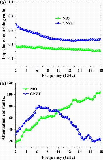
It is widely accepted that excellent microwave absorption performance of materials requires a good impedance matching and a strong attenuation capability, which are closely related to complex permittivity, complex permeability, specific conductance, thickness, and structure of absorber [1, 50]. In the first place, the impedance characteristic has a direct influence on the microwave absorption efficiency. This is because EM waves should efficiently penetrate the materials with minimized reflection at the interfaces. In other words, the impedance characteristic of absorbers should be infinitely close to that of free space. Figure 8a illustrates the impedance matching ratios of the NiO and CNZF composites. As observed, CNZF has a more suitable impedance matching ratio over the whole frequency region (2-18 GHz), as compared with the NiO sample. In fact, the impedance matching ratios of both the NiO and CNZF samples are higher than 0.3 [51]. Meanwhile, the attenuation constant α has been studied to analyze their attenuation performances, which are shown in Fig. 8b. The attenuation constant α indicates an integral loss effect including dielectric loss and magnetic loss, which is given by [52]:
Fig. 8 a Impedance matching ratio, b attenuation constant α of the NiO and CNZF composites
$\alpha = \frac{\sqrt 2 \pi f}{c} \times \sqrt {(\mu^{{\prime \prime }} \varepsilon^{{\prime \prime }} - \mu^{{\prime }} \varepsilon^{{\prime }} ) + \sqrt {(\mu^{{\prime \prime }} \varepsilon^{{\prime \prime }} - \mu^{{\prime }} \varepsilon^{{\prime }} )^{2} + (\mu^{{\prime }} \varepsilon^{{\prime \prime }} - \mu^{{\prime \prime }} \varepsilon^{{\prime }} )^{2} } } .$ (5)
As shown in Fig. 8b, NiO has a high attenuation constant α at high frequency range (~10-18 GHz), while at lower frequency region (~2-10 GHz), CNZF presents a relatively higher attenuation constant α. Both NiO and CNZF samples show great attenuation abilities in the frequency range of 6-12 GHz. Therefore, it is reasonable to obtain the maximum RL peaks of the double-layer absorbers composed of the absorption layer filled with CNZF and the matching layer filled with NiO located in these frequency ranges, due to the synergistic absorbing effect of the NiO and CNZF layers. In one word, the high impedance matching ratio and the large attenuation constant α render the excellent microwave absorption capabilities for double-layer absorbers in a small thickness.
Hierarchical spherical NiO particles were prepared by using a hydrothermal method, and CNZF ferrites were synthesized by using a sol-gel autoignition method. Electromagnetic and microwave absorption properties of these samples were systematically studied. Due to the high impedance matching characteristic, large attenuation capability, and well-coupled layer, the double-layer absorbers, with the CNZF composite as the absorption layer and NiO composite as the matching layer, showed promising RL values, wider absorbing bandwidths, and smaller thicknesses, as compared with the individual single-layer absorbers. With the optimal total thickness of 3.2 mm, the absorber exhibited a maximum RL value of -67.0 dB at 9.2 GHz and an effective bandwidth below -10 dB to be 3.9 GHz (7.0-10.9 GHz). It is believed that these new double-layer absorbers could be promising candidates as advanced microwave materials for various practical applications.
This work was financially supported by the Priority Academic Program Development of Jiangsu Higher Education Institutions (PAPD), the Opening Project of Jiangsu Key Laboratory of Advanced Structural Materials and Application Technology (ASMA201405), the National Natural Science Foundation of China (51672129), and Singapore MOE AcRF Tier 1 Project (Research ID 477).
The authors have declared that no competing interests exist.

 WeChat
/
| 〈 |
|
〉 |