Acta Metallurgica Sinica(English Letters), 2017, 33(5): 481-486
doi: 10.1016/j.jmst.2016.09.003
Mechanical Property, Oxidation and Ablation Resistance of C/C-ZrB-ZrC-SiC Composite Fabricated by Polymer Infiltration and Pyrolysis with Preform of C/ZrB
Dong Huang1, Mingyu Zhang2,*, Qizhong Huang2,*,, Liping Wang2, Kai Tong2

Abstract:

C/C-ZrB2-ZrC-SiC composites were fabricated by polymer infiltration and pyrolysis (PIP) with a preform of Cf/ZrB2. The carbon fibers and the resin carbon were coated with ceramic layer after PIP in the composites. The composite presents a pseudo-plastic fracture due to deflection of cracks and pullout of fibers. The composite has a higher bending strength by this method in comparison with the conventional PIP process due to fewer heat treatment cycles. The static oxidation test shows that the mass loss of the composites is no more than 1% after 20 min oxidation at 1100 °C. The “core-shell” structure between ZrC-SiC ceramic and other phases plays a positive role in preventing the inward diffusion of oxygen. The ablation resistance of the C/C-ZrB2-ZrC-SiC composite samples was tested using a plasma generator. After ablation for 120 s, the mass and linear ablation rates of the composites are 4.65 mg cm-2 s-1 and 2.46 µm s-1, respectively. The short carbon layer shows a better ablation resistance than the nonwoven carbon fabric layer after the ceramic coating is peeled off because of its higher ceramic content.

Key words: C/C composite; Ceramic-matrix composites; High temperature corrosion;
1. Introduction

Carbon/Carbon (C/C) composites are one of the most promising materials for high temperature structural applications due to their low coefficient of thermal expansion (CTE), high thermal conductivity, excellent strength at high temperature, good ablation resistance and good thermal shock resistance[1,2,3]. They have been widely used in high temperature structural components for space vehicles, such as rocket nozzles, nose tips, aeronautic jet engines, and leading edges. However, poor oxidation resistance (above 500 °C) and a severe ablative environment (high-pressure gas and high velocity grains) have greatly restricted their high temperature applications[4,5,6,7,8,9,10]. Therefore, effective thermal protection is essential when they are used in an oxygen environment at high temperature.

The introduction of Zr-based ceramics (such as ZrB2 and ZrC) and SiC into C/C composites can improve the thermal protection of the C/C composites because they can form a less volatile and high melting point Zr-Si-O glass layer[11,12,13,14,15,16]. Reactive melt infiltration can introduce Zr-based ceramic and SiC into the C/C composites and improve their ablation resistance[10,17,18]. However, the composites prepared exhibit poor mechanical properties due to the carbothermic reaction between the carbon substrate and the raw powders (Si, Zr, etc.). Powder slurry infiltration (PSI) is a low cost method of introducing ceramic phase into the composite, but the poor distribution of ceramic phases cannot be resolved as yet, especially for large components[11,19,20,21]. It is also difficult to fabricate complex shapes or large components by hot-press and sinter processing[22]. In comparison, polymer infiltration and pyrolysis (PIP) is an ideal modification method because the use of organic precursor to introduce ceramics into C/C composites could improve not only the content but also the distribution homogeneity of ceramics in the composite[23,24,25,26,27]. However, it remains a challenge to reduce the number of PIP cycles when a large amount of Zr-based ceramics is introduced into C/C composite. It is believed that dozens of the heat treatment cycles degrade the flexural strength due to the reaction between the precursor and the carbon fibers.

In previous study[28], we reported a novel C/C-ZrB2-ZrC-SiC composite fabricated by PIP using a carbon fiber preform containing ceramic powders (Cf/ZrB2). This method uses less heat treatment cycles than the conventional PIP process. Therefore, the C/C-ZrB2-ZrC-SiC composite prepared is supposed to have a higher bending strength due to less carbothermic reaction between the precursor and the carbon fibers. The ZrC-SiC ceramics and other phases form the “core-shell” structures, which are believed to play a positive role in oxidation resistance. Although many data have been reported in literature on thermal protection of the composites, there are few reports about the effect of the “core-shell” structure on oxidation resistance. Because the Cf/ZrB2 preform is composed of alternating layers of the nonwoven carbon fabric and the short carbon fibers in the needled direction, the ablation characteristics of the composite in both layers are different and should be studied.

In the present work, the microstructure, mechanical behavior, oxidation resistance and ablation characteristics of the C/C-ZrB2-ZrC-SiC composites in the special layers were investigated to further assess the usage of the materials.

2. Experimental Procedures
2.1. Materials preparation

The detailed fabrication process of the Cf/ZrB2 preform and the C/C-ZrB2-ZrC-SiC composite is shown in our previous study[28]. The C/C-ZrB2-ZrC-SiC composites were fabricated by the following three-step method. Firstly, the Cf/ZrB2 preform with a density of 0.50 g/cm3 was prepared by a repeated spraying-needling process. Secondly, the resin carbon was introduced into the Cf/ZrB2 preform to increase its density by vacuum impregnation and carbonization. The porous C/C-ZrB2 composites with a density of 1.49 g/cm3 were obtained. Finally, the mixture of ZrC-SiC ceramics was introduced into the as-prepared C/C-ZrB2 composites by PIP. This infiltration-pyrolysis process was repeated 6-8 times until the density of the C/C-ZrB2-ZrC-SiC composites reached 1.98 g/cm3. The C/C-ZrC-SiC composite fabricated by pure PIP (17-20 cycles) was used as a control group.

2.2. Characterizations

The flexural strength was obtained by using a three-point bending test (Instron-3369) on five specimens of 4 mm × 10 mm × 55 mm with a span of 48 mm and a loading velocity of 0.5 mm/min. The oxidation resistance of samples was evaluated by the static oxidation in a muffle furnace. The samples were put into the furnace and heated at 1100 °C for several minutes. After cooling down to room temperature, the samples were measured using an electrical balance with the accuracy of 0.1 mg. The ablation resistance of the C/C-ZrB2-ZrC-SiC composite samples of a cylindrical shape (Ø 30 mm × 10 mm) was tested using a plasma generator (Multiplaz, 3500). The erosion direction of the flame and the axial orientation of the samples were parallel to the Z direction of the carbon felts (the needled direction). The working current and voltage of the plasma generator were 6 A and 160 ± 1 V, respectively. The inner diameter of the plasma gun tip was 2 mm, and the distance between the gun tip and the sample was roughly 10 mm. The samples were exposed to the flame, and the maximum temperature of the ablation center reached up to 2300 °C, which was measured by an optical pyrometer. Both the linear and mass ablation rates were calculated based on the mean thickness and mass change in the ablated center of the samples before and after ablation. More than five tests were conducted for each sample, and the presented results are the averages of these ablation rate measurements. The bulk density of the samples was measured using the Archimedes method. The microstructure of the composites was characterized by scanning electron microscopy (SEM, FEI Nova Nano SEM230), backscattered electron imaging analysis (BSE, FEI Nova Nano SEM230), X-ray diffraction (XRD, Rigaku Dmax/2550VB + 18KW) and electron probe microanalysis (EPMA, JEOL JXA-8530F).

3. Results and Discussion
3.1. Microstructure

Fig. 1(a) shows SEM image of the composite surface. After PIP process, the composites have a compact surface, and something like ceramic residues is present on the surface. The ceramic residues form a ceramic coating on the carbon phase, which acts as a ceramic “shell” on the “core” of the carbon phases. Both cracks and pores can also be observed on the surface. XRD pattern of the C/C-ZrB2-ZrC-SiC composites (Fig. 2(b)) reveals that the surface of the composites is mainly composed of ZrC and SiC. C peak is also observed, which indicates that the composite is not completely covered by the ceramic layer. BSE image also shows that most of the surface is covered with the ZrC-SiC ceramic (gray white part). Carbon phase (black part) can also be observed, which is agreed with XRD analysis (Fig. 1(b)).

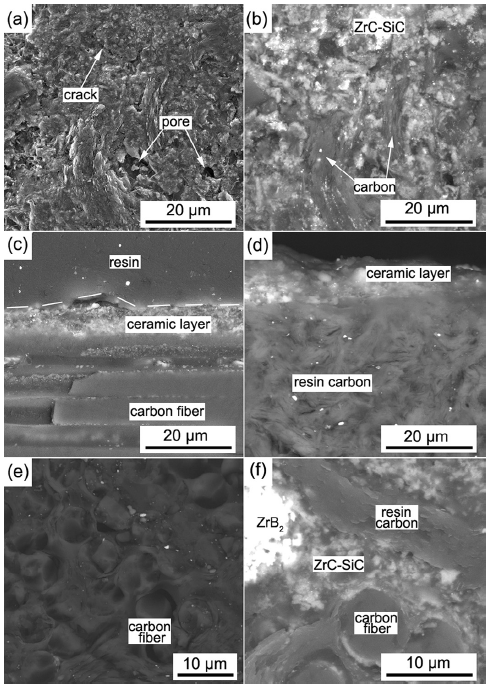
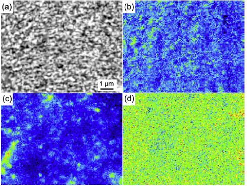
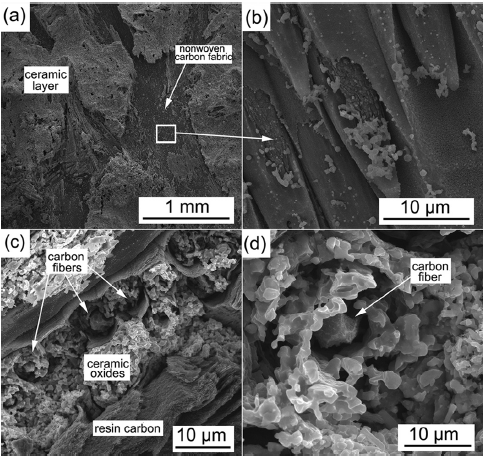
Fig.1. Microstructure of the C/C-ZrB2-ZrC-SiC composites: (a) SEM image of surface; (b) BSE image of surface; (c) the outside ceramic coating on the nonwoven carbon fabric layer; (d) the outside ceramic coating on the short carbon fibers layer; (e) nonwoven carbon fabric layer; (f) short carbon fibers layer.

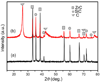
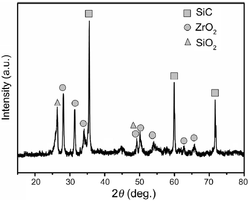
Fig.2. XRD patterns of the ZrC-SiC precursors heat-treated at 1700 °C (a) and surface of the C/C-ZrB2-ZrC-SiC composites (b).

Fig. 1(c and d) shows the outside ceramic coating (ZrC-SiC “shell”) on the nonwoven carbon fabric layer and short carbon fibers layer, respectively. The thickness of ZrC-SiC layer is about several micrometers. The outer ZrC-SiC “shell” integrates tightly with the carbon phase substrate, which can prevent the inward diffusion of oxygen. Because pores among fibers are small and filled with resin carbon, there is almost no open pore left in nonwoven carbon fabric layer. No white part or gray white part (color of ceramic phase) is found in the BSE image of the nonwoven carbon fabric layer (Fig. 1(e)). Therefore, there are few ZrC-SiC ceramics filled in this region after PIP. Fig. 1(f) shows the microstructure of short carbon fibers layer in the composites. More ceramic phases (white part) can be observed in the layer because of more open pores. It also can be observed that the ZrB2 power, resin carbon and carbon fiber are all coated with ZrC-SiC ceramics after PIP process. And two kinds of “core-shell” structure are formed: “ZrC-SiC coated carbon phase (carbon fiber and resin carbon)” and “ZrC-SiC coated ZrB2”. The first kind of “core-shell” structure can protect the carbon phase from corrosion, while the second kind of “core-shell” structure can provide more ablation-resistant components (ZrB2) for the composite (more on this later).

XRD pattern of SiC-ZrC precursors heat-treated at 1700 °C is shown in Fig. 2(a). The sharpening of characteristic peaks of SiC and ZrC is noticeable, and no characteristic peak related to any other phase is observed. EPMA analysis (Fig. 3) is used to elucidate the microstructural features and elemental distributions of the ZrC-SiC ceramic in the composite. It can be seen that the contents of Si and Zr disperse uniformly in the ceramic phase. The uniform mixture of SiC particles and ZrC particles is beneficial to the formation of the high temperature Zr-Si-O glass during ablation.

Fig.3. EPMA analysis of the ceramic matrices: (a) BSE images, (b) C distribution, (c) Si distribution, (d) Zr distribution.

3.2. Mechanical property

The stress-displacement curve (Fig. 4) indicates that the C/C-ZrB2-ZrC-SiC composites present a pseudo-plastic fracture without catastrophic failure in bending process. The bending strengths of the C/C-ZrB2-ZrC-SiC composites and the C/C-ZrC-SiC composites are 145.3 MPa and 85.5 MPa, respectively (Table 1). The mixture of polymeric organic ZrC precursor contained 12.6 wt% O[28], so the reactant can be seen as an oxidant during heat treatment. The oxidant inevitably reacts with the carbon fiber (as a reductant) during carbothermic reaction when the ceramic matrix is formed. Then the strength of the carbon fiber decreases. Therefore, the bending strength of the composite will become smaller, if the composite is subjected to more heat treatments. However, the bending strength loss of the C/C-ZrB2-ZrC-SiC composites is not so much compared to pure PIP process (17-20) due to the fewer heat treatments (6-8). Because small amounts of ceramics are formed between the nonwoven carbon fabric layer and the short carbon layer after PIP, the outside carbon fibers in the carbon fabric layer are also covered with ceramic matrices. Fig. 5(a) shows that carbon fibers in the nonwoven carbon fabric layer are pulled out in the fracture section. Because the interface bonding between fibers and ceramics is weak, the crack can deflect easily along the interface (Fig. 5(b)). Therefore, the C/C-ZrB2-ZrC-SiC composite shows a pseudo-ductile fracture behavior.

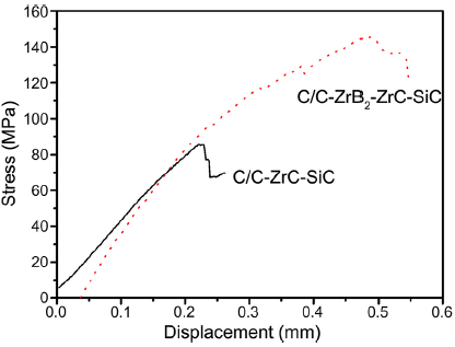
Fig.4. Stress displacement curves of bending load for C/C-ZrB2-ZrC-SiC composite and C/C-ZrC-SiC composite.


Table 1. Properties comparison of C/C-ZrC-SiC and C/C-ZrB2-ZrC-SiC composites
Sample PIP cycles Density (g/cm3) Bending strength (MPa) Mass ablation rate (120 s) (mg cm-2 s-1) Linear ablation rate (120 s) (µm s-1)
C/C-ZrC-SiC 17-20 2.01 85.5 13.15 ± 0.07 6.84 ± 0.08
C/C-ZrB2-ZrC-SiC 6-8 1.98 145.3 4.65 ± 0.12 2.46 ± 0.05

Table 1. Properties comparison of C/C-ZrC-SiC and C/C-ZrB2-ZrC-SiC composites

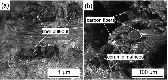
Fig.5. Fracture surfaces the C/C-ZrB2-ZrC-SiC composite: (a) BSE image of the fracture surface of the C/C-ZrB2-ZrC-SiC composites; (b) higher magnification image.

Isothermal oxidation tests at 1100 °C and 1500 °C in static air are often used to assess the oxidation resistance of the coating samples. As for matrix modification in this study, the temperature (1100 °C) when the oxides cannot heal the cracks or pores is adopted in order to understand the effect of structure defect on oxidation resistance. Fig. 6 shows the comparison of the isothermal oxidation curve between the C/C-ZrB2-ZrC-SiC and the C/C composite. It is of note that the mass loss is no more than 1% in the first 20 min, which is sufficient for short time ablation (several hundred seconds). After 60 min oxidation in static air at 1100 °C, the mass loss of the C/C-ZrB2-ZrC-SiC is 10.96%, while that of C/C composite is 34.56%. These results indicate that the oxidation resistance of the C/C-ZrB2-ZrC-SiC composites is improved in comparison with C/C composites.

Fig.6. Isothermal oxidation test of the C/C and C/C-ZrB2-ZrC-SiC composite at 1100 °C in static air.

The microstructure of C/C-ZrB2-ZrC-SiC composites after oxidation at 1100 °C is shown in Fig. 7. It reveals that a loose ceramic layer forms on the oxidized surface. Both micro-pores and cracks can be seen on the ceramic layer, providing a channel for oxygen diffusion toward carbon phase (Fig. 7(a)). The higher magnification image (Fig. 7(b)) shows that the ceramic grains are coral-like stacking with some micro-pores. XRD analysis (Fig. 8) also confirms that the glass oxides layer is composed of ZrO2 and SiO2 due to the oxidation of the ZrC-SiC ceramic “shell”. No C phase is detected, indicating that the ceramic layer is not destroyed. Therefore, the ceramic layer in the “core-shell” structure can prevent oxygen from reacting with carbon phase and improves the oxidation resistance of the composite.

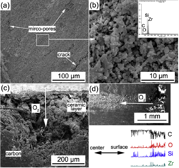
Fig.7. 7. Microstructure of the surface of the C/C-ZrB2-ZrC-SiC composites after oxidation: (a) surface; (b) high magnification image of the area framed by white line in (a); (c) cross section; (d) line scan of EDS shows the diffusion of O2 in ceramic matrices.

Fig.8. XRD pattern of the surface of the C/C-ZrB2-ZrC-SiC composites after oxidation.

Fig. 7(c) shows the corrosion pit at the interface between the outer ceramic “shell” and the inner carbon phase after oxidation. Through the structural defects (cracks or pores) of the ceramic layer, the oxygen diffuses toward the ZrC-SiC/C interface and reacts with carbon phase. Therefore, carbon phase is oxidized below at the bottom of the pit, and becomes a loose structure. Fig. 7(d) shows the diffusion of oxygen in ceramic matrix (ZrC-SiC and ZrB2). A linear scan of oxygen density indicates that the contents of O decrease from the outer part to the inner part of the ceramic matrix, indicating that the inner part of the composite has not been oxidized. It is believed that the carbon phase is not oxidized until the ZrC-SiC ceramic “shell” is damaged. The “core-shell” structure plays a positive role in improving the oxidation resistance because it can prevent the inward diffusion of oxygen.

3.3. Ablation resistance

The ablation resistance of the composite samples was tested for 120 s at over 2300 °C using a plasma generator as the ablation equipment. It is clear that these samples exhibit good ablation resistance (Table 1). After ablation for 120 s, the mass and linear ablation rates of the samples are 4.65 mg cm-2 s-1 and 2.46 µm s-1, respectively.

Fig. 9. Microstructure of the ablated center of the composites after 120 s ablation: (a) surface. (b) cross section.

Fig. 9 shows the microstructural features of the ablated center of the composites after 120 s ablation. The surface is covered with a glass layer, which is composed of ZrO2 and SiO2 due to the oxidation of ZrB2, ZrC and SiC. It is known that SiO2 has a low melting point (<1700 °C), which is far below the ablation temperature. However, the glass layer is not destroyed, because the SiO2 reacts with ZrO2 to form high temperature Zr-Si-O glass according to SiO2-ZrO2 phase diagram[26]. The Zr-O-Si glass covers on the composites, and prevent them from corrosion because of its higher melting point. Many small pores are observed in the glass layer, because the gaseous products (COn, SiO2 and B2O3) move out of the composite. The SEM image of the cross section of the surface (Fig. 9(b)) also reveals that the carbon fibers are well protected by the glass layer, and no hollow pores and tip-sharp carbon fibers are observed.

It is noted that the composite is composed of alternating layers of the nonwoven carbon fabric and the short carbon fibers in the needled direction (Fig. 10(a)), both of which may appear on the surface after machining. Fig. 10(b and c) shows the schematic diagram of the ablation of the nonwoven carbon fabric layer and the short carbon layer, respectively. In order to further understand the ablation characteristic, the structures of nonwoven carbon fabric layer and short carbon layer are analyzed after the ceramic layers are peeled off.

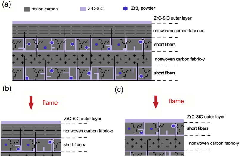
Fig.10. Schematic diagram of the ablation test: (a) C/C-ZrB2-ZrC-SiC composite; (b) ablation in nonwoven carbon fabric layer; (c) ablation in short carbon fibers layer.

Although some glassy residues remain on the surface after the ceramic coating is destroyed, these glassy residues cannot form a continuous ceramic layer (Fig. 11(a)). The carbon fibers in nonwoven carbon fabric layer are exposed to the plasma torch and thus ablated due to the oxidation and scouring. High magnification image (Fig. 11(b)) shows that the carbon fibers are wedge-like after ablation. The corrosion of the C/C-ZrB2-ZrC-SiC composite in the nonwoven carbon fabric layer is similar to that of the pure C/C composite. Ablation preferentially takes place at the interface between the resin carbon and the carbon fiber because of its high activation. In comparison with the nonwoven carbon fabric layer, there are more ceramics in the short carbon fibers layer (Fig. 1). When the glassy layers on the surface are peeled off, the ceramic oxides can also be observed around the carbon fibers and resin carbon (Fig. 11(c)). The ceramic oxide exhibits a loose structure due to the erosion of high temperature torch, and fills large pores between the resin carbon and carbon fiber. High magnification image (Fig. 11(d)) shows that the carbon fiber in the short carbon fibers layer is subject to slighter corrosion than that in the nonwoven carbon fabric layer after ablation. The ceramic oxide, which has a small oxygen diffusion coefficient and a high melting point, coats the carbon fiber and prevents it from ablation and oxidation. Actually, the linear ablation rate of the composite after ablation for 240 s is 3.35 µm s-1[28]. It is higher than the rate after ablation for the first 120 s (2.46 µm s-1), because the nonwoven fabric layer in the composite is ablated.

Fig.11. Microstructure of the nonwoven carbon fabric layer and the short carbon layer after the ceramic coating is peeled off: (a) nonwoven carbon fabric layer; (b) high magnification of (a); (c) short carbon layer; (d) high magnification of (c).

4. Conclusion

The C/C-ZrB2-ZrC-SiC composite was fabricated by PIP with a preform of Cf/ZrB2. The carbon fibers and the resin carbon were coated with ceramic layer after PIP in the composites. The composite presents a pseudo-plastic fracture due to deflection of cracks and pullout of fibers. In comparison with pure PIP, the C/C-ZrB2-ZrC-SiC composite possesses a higher bending strength, and the bending strength is 145.3 MPa. The ZrC-SiC coating in the “core-shell” structure improves oxidation resistance of the C/C-ZrB2-ZrC-SiC composite. After 20 min static oxidation in the air at 1100 °C, the mass loss is no more than 1%. After ablation for 120 s, the mass and linear ablation rates of the samples are 4.65 mg cm-2 s-1 and 2.46 µm s-1, respectively. The short carbon layer shows a better ablation resistance than the nonwoven carbon fabric layer after the ceramic coating is peeled off because of its higher ceramic content.

Acknowledgments:This work was financially supported by the National Natural Science Foundation of China (No. 51404041) and the Natural Science Foundation of Hunan Province (No. 2015JJ3016).

The authors have declared that no competing interests exist.

References

[1] E. Fitzer, Carbon 25 (1987) 163-190.
[Cited within:1]
[2] J.E. Sheehan, K.W. Buesking, B.J. Sullivan, Annu. Rev. Mater.Sci. 24(1994) 19-44.
[Cited within:1]
[3] G.L. Vignoles, Y. Aspa, M. Quintard, Compos. Sci. Technol. 70(2010) 1303-1311.
[Cited within:3]
[4] D. Huang, M. Zhang, Q. Huang, L. Xue, P. Zhong, L. Li, Corros. Sci. 87(2014)134-140.
[Cited within:1]
[5] Y.Wang, H. Li, Q. Fu, H.Wu, L. Liu, C. Sun, Ceram. Int. 39(2013) 359-365.
[Cited within:1]
[6] C. Ni, K. Li, L. Liu, H. Li, Q. Fu, L. Guo, N. Liu, Corros. Sci. 84(2014) 1-10.
[Cited within:1]
[7] Y. Ma, Q. Li, S. Dong, Z. Wang, G. Shi, H. Zhou, Z. Wang, P. He, Ceram. Int. 40(2014) 11387-11392.
[Cited within:1]
[8] K. Li, X. Shen, H. Li, S. Zhang, T. Feng, L. Zhang, Carbon 49 (2011) 1208-1215.
[Cited within:1]
[9] L.C. Erica, S.W. Luke, J. Eur.Ceram.Soc. 30(2010) 2357-2364.
[Cited within:1]
[10] Y.Wang, X. Zhu, L. Zhang, L. Cheng, Ceram. Int. 37(2011) 1277-1283.
[Cited within:2]
[11] C. Sun, H. Li, Q. Fu, J. Zhang, Corros. Sci. 79(2014) 100-107.
[Cited within:2]
[12] X. Shen, L. Liu,W. Li, K. Li, Ceram. Int. 41(2015) 11793-11803.
[Cited within:1]
[13] L. Zhuang, Q. Fu, J. Zhang, Y. Guo, H. Li, Y. Shan, Ceram. Int. 41(2015) 6956-6964.
[Cited within:1]
[14] C. Yan, R. Liu, Y. Cao, C. Zhang, D. Zhang, Ceram. Int. 40(2014) 10961-10970.
[Cited within:1]
[15] H. Li, L. Zhang, L. Cheng, Y.Wang, Ceram. Int. 35(2009) 2831-2836.
[Cited within:1]
[16] C. Hu, S. Pang, S. Tang, S. Wang, H. Huang, H. Cheng, Corros. Sci. 80(2014)154-163.
[Cited within:1]
[17] Y. Tong, S. Bai, K. Chen, Ceram. Int. 38(2012) 5723-5730.
[Cited within:1]
[18] Z. Li, H. Li, S. Zhang, K. Li, Ceram. Int. 38(2012) 3419-3425.
[Cited within:1]
[19] D.D. Jayaseelan, R.G. de Sá,P. Brown, W.E. Lee, J. Eur. Ceram. Soc. 31(2011)361-368.
[Cited within:1]
[20] H. Hu, Q. Wang, Z. Chen, C. Zhang, Y. Zhang, J. Wang, Ceram. Int. 36(2010)1011-1016.
[Cited within:1]
[21] S. Tang, J. Deng, S.Wang,W. Liu, Corros. Sci. 51(2009) 54-61.
[Cited within:1]
[22] L. Zhao, D. Jia, X. Duan, Z. Yang, Y. Zhou, J. Eur. Ceram.Soc. 32(2012) 947-954.
[Cited within:1]
[23] J. Xie, K. Li, H. Li, Q. Fu, L. Guo, Ceram. Int. 39(2013) 4171-4178.
[Cited within:1]
[24] K. Li, J. Xie, Q. Fu, H. Li, L. Guo, Carbon 57 (2013)161-168.
[Cited within:1]
[25] C. Liu, L. Cao, J. Chen, L. Xue, X. Tang, Q. Huang, Carbon 65 (2013) 196-205.
[Cited within:1]
[26] B. Feng, H. Li, Y. Zhang, L. Liu, M. Yan, Corros. Sci. 82(2014) 27-35.
[Cited within:2]
[27] Q. Li, S. Dong, Z. Wang, P. He, H. Zhou, J. Yang, B. Wu, J. Hu, J. Am.Ceram.Soc.95(2012) 1216-1219.
[Cited within:1]
[28] D. Huang, M. Zhang, Q. Huang, L. Wang, L. Xue, X. Tang, K. He, Corros. Sci. 98(2015) 551-559.
[Cited within:4]
Downloaded    
RichHTML Viewed    
Abstract Viewed    

Share
Export

Related articles:
Key words
C/C composite
Ceramic-matrix composites
High temperature corrosion

Authors
Dong Huang
Mingyu Zhang
Qizhong Huang
Liping Wang
Kai Tong