Search for articles:
Ren-Guo Guan , Di Tie
Corresponding authors:
Received: 2016-10-8
Revised: 2017-03-1
Online: 2017-05-20
Copyright: 2017 Editorial board of Acta Metallurgica Sinica(English Letters) Copyright reserved, Editorial board of Acta Metallurgica Sinica(English Letters)
More
Abstract
Aluminum becomes the most popular nonferrous metal and is widely used in many fields such as packaging, building transportation and electrical materials due to its rich resource, light weight, good mechanical properties, suitable corrosion resistance and excellent electrical conductivity. Grain refinement, which is obtained by changing the size of grain structure by different techniques, is a preferred method to improve simultaneously the strength and plasticity of metallic materials. Therefore, grain refining of aluminum is regarded as a key technique in aluminum processing industry. Up to now, there have been a number of techniques for aluminum grain refining. All the techniques can be classified as four categories as follows: grain refining by vibration and stirring during solidification, rapid solidification, the addition of grain refiner and severe plastic deformation. Each of them has its own merits and demerits as well as applicable conditions, and there are still some arguments in the understanding of the mechanisms of these techniques. In this article, the research progresses and challenges encountered in the present techniques and the future research issues and directions are summarized.
Keywords:
Aluminum becomes the most popular nonferrous metal and is widely used in many fields due to its rich resource, light weight, good mechanical properties, suitable corrosion resistance and excellent electrical conductivity. All the mentioned advantages are positive deciding factors for designers, manufacturers and industrial users who are always on the lookout for better-performing materials and innovative processes. Current industrial applications of aluminum alloys include but not limited to aerospace, automotive, marine, building, packaging, mechanical industry, 3C and energy distribution [1, 2]. In January 2015, the European Commission issued the European Metallurgical Roadmap of 2050. Its long-term goal was to develop metals and metal-based matrix composites with high strength, high ductility, corrosion and wear resistance and to give priority to improve the strength, formability and corrosion resistance of 2, 5, 6 and 7 series aluminum alloys as well as to expand the use of heat-resistant aluminum alloys [3]. In addition, high-strength aluminum alloy was listed as one of the key development plans in Advanced Manufacturing Partnership (AMP) of the USA [4]. Aluminum Industry Roadmap of 2020 was also put forward by the Aluminum Industry Association of the USA [5]. The goal was to reduce aluminum production costs by 25%, energy consumption by 25% and to develop a new generation of aluminum alloy materials with zero pollution emissions [5]. United States Council for automotive materials had made the aluminum alloy industry roadmap as well. According to this plan, in order to expand the application of aluminum alloy in automobile industry, the corrosion, design, preparation, processing, microstructure control and material jointing of aluminum alloys would be comprehensively studied [6, 7, 8]. Besides the mentioned traditional usages, Al has been used as matrix materials in metal matrix composites fabricated stir casting, powder metallurgy and mechanical milling as well [9, 10, 11, 12].
With increasing demands for better mechanical performance of aluminum alloys, various technologies were applied during the past decades for achieving higher strength as well as ductility of aluminum alloys [13], among which purifying and grain refinement were two key issues according to their outstanding effects on improving aluminum products’ mechanical performance. Similar as the importance of purifying in melting process, grain refinement is crucial for the products’ mechanical properties during and after solidification process. Grain refinement becomes a preferred method to improve simultaneously the strength and plasticity of metallic materials. The most evident improvement brought by grain refinement is elevated strength at room temperature, which can be theoretically explained by the Hall-Petch relation (Eq. 1) [14]:
$$\sigma_{\text{y}} = \sigma_{0} + k_{\text{y}} \cdot d^{{ - \frac{1}{2}}}, \ \ (1)$$
where σy is the yield stress, σ0 is a material constant of the starting stress for dislocation movement (or the resistance of the lattice to dislocation motion), ky is the strengthening coefficient (a constant specific to each material), and d is the average grain diameter. Hall-Petch strengthening (or grain boundary strengthening) is an important method of strengthening materials by grain refining; meanwhile, ductility is improved with increasing grain numbers. Compared with precipitation strengthening and deformation hardening, grain refinement can simultaneously improve strength, toughness and ductility and reduce casting defects, such as segregation and porosity. Moreover, it eliminates the columnar structure and therefore improves the quality of wrought alloys through improving formability. Grain refinement playing an important role in both cast and wrought aluminum alloys was gradually realized with aluminum’s application in industry. Reduced mechanical properties have been noted in plate products when as-cast grain is not fine and uniform [15]. It has been reported that twinned columnar grains reduced the formability, yield strength and tensile elongation to fracture of alloy [16], and a coarse microstructure may result in a variety of surface defects in alloys used in rolled or extruded form for applications [17]. Besides, hot cracking in the shell zone of a cast ingot is more severe if the grain structure is not equiaxed or fine [18]. An equiaxed structure allows a high casting rate to be achieved before hot crack occurring. There are also several other benefits from grain refinement, such as homogenous distribution of second phases, microporosity in a fine scale, better feeding to eliminate shrinkage porosity, improved ability to achieve a uniform anodized surface, better strength and fatigue life [19]. Therefore, most cast aluminum products with high mechanical performance are grain refined currently [20].
The development of grain refinement is shown in Table 1. Grain refining can be carried out during and after solidification process. These methods could be classified into four categories, namely grain refining by vibration and stirring (VS) during solidification, rapid solidification (RS), the addition of grain refiner (GR) and severe plastic deformation (SPD). It is taken for granted that grain refining by vibration and stirring is due to dendritic arm breakage under shear force induced by VS. Despite majority of researchers’ agreement to this viewpoint, it was still argued by some other scholars. Actually, the heterogeneous nucleation on the mold wall and convection could contribute to grain refinement. Moreover, mechanism of liquid infiltration in grain boundary induced by plastic bending of dendrite arm and re-melting of dendritic root induced by ripening and stirring was further put forward [21]. These disputes may be lasted for a long time. Further exploring, these issues may broaden the field of technology and bring about a revolution in condensed materials.
Table 1 Development of grain refinement methods
| Date | Severe plastic deformation | Grain refiner | Rapid solidification | Vibration and stirring |
|---|---|---|---|---|
| 2000 years ago | Multi-directional forging | |||
| 1857 | Twin-roll casting [26] | |||
| 1870s | Mechanical vibration [27] | |||
| 1920s | High-pressure die casting [28] | |||
| 1930s | Ultrasonic vibration [29] | |||
| 1937 | Liquid forging technique [30] | |||
| 1941 | Gas atomization [31] | |||
| 1947 | Electromagnetic stirring [32] | |||
| 1950s | Al-Ti-B [33] | |||
| 1958 | Melt spinning [34] | |||
| 1968 | Spray deposition [35] | |||
| 1977 | Equal-channel angular pressing [36] | |||
| 1979 | Cyclic extrusion-compression [37] | |||
| 1980s | Al-Ti-C [5] | |||
| 1989 | High-pressure torsion [38] | |||
| 1991 | Friction stir welding [39] | |||
| 1996 | Cooling slope [40] | |||
| 1998 | Accumulative roll-bonding [41] | |||
| 1999 | Twist extrusion [42] | |||
| 2001 | Repetitive corrugation and straightening [43] | |||
| 2007 | Vibrating cooling slope [44] | |||
| 2014 | Tube cyclic extrusion [45] | |||
| 2015 | Accumulative continuous extrusion forming [46] |
Subjected to solidification theory, a number of rapid solidification methods were developed for grain refining and metal glass (MG) preparation. Some of them, for instance, roll casting and spray deposition have been successfully used in industries for producing high-performance materials, but there were still issues in application, such as the purity, the efficiency and cost were not satisfactory [22].
It is now accepted that the presence of both potent nucleant particles and sufficient solutes are essential for effective grain refining during solidification process [23]. Despite the common recognition of these two essentials, the details of grain refinement mechanisms have still some ambiguities. One of the major problems is to determine the exact factors that control the efficiency of grain refinement. It appears that something important is still missing in the current understanding of grain refinement. It is worth noting that the spotlight of previous studies on grain refinement mechanism of aluminum was primarily focused on the Al-Ti-B and Al-Ti-C systems as they are the most common grain refiners used in the foundry [24]. However, it is believed that other solute elements may also produce effective grain refinement in Al, which may provide fresh insight into the factors that control the grain refining efficiency [25].
Grain refinement of aluminum in solid state generally relies on recrystallization which can be mostly achieved by classical thermo-mechanical treatment and severe plastic deformation technologies. It should be noted, for heat treatable aluminum alloys, deformation hardening and precipitation strengthening also provide important contribution to alloy strengthening, but these factors may decrease the material’s ductility. As far as thermo-mechanical treatment is concerned, a wide variety of conventional heat treatment processes have been developed and used in industry. In severe plastic deformation (SPD), high strain is imposed on metal samples using special tools, so that free flow is prevented and large deformation occurs under a hydrostatic pressure [47]. A critical requirement in SPD processing is that the material experiences a very high strain without introducing any significant changes in the overall dimensions of the workpiece. Actually, SPD method had successfully been applied to manufacture high-performance sword in ancient times, which is now called multi-direction forging. Its principle lies in the recrystallization that is induced by multi-direction forging and thermal action. Although the history of this type of processing may be traced back more than 2000 years ago to the metal-working practices of ancient China, the principle of SPD was revealed within the last few decades with the help of sophisticated analytical tools. According to this principle, a variety of SPD methods were developed and ultra-fine and nano-grained materials were successfully prepared. Processing by SPD is now a favorable procedure for the fabrication of bulk solids with exceptionally small grain sizes. However, most SPD methods face the challenges like long processing time, high cost and low efficiency. Therefore, dealing with these problems becomes an important issue, which is crucial for the development of aluminum processing industry.
Up to now, there have been a lot of techniques developed for aluminum grain refining, but a systematic summary of these methods is still absent. The main objective of the present review is to summarize the primary types of technologies currently applied for grain refining of aluminum alloys: grain refining by vibration and stirring (VS) during solidification, rapid solidification (RS), the addition of grain refiner (GR) and severe plastic deformation (SPD). Each of them has its own merits and demerits as well as applicable conditions, and there are still some arguments in the understanding of the mechanisms of these techniques. This article reviews the latest research progresses and challenges encountered in the present techniques, and the future research issues and directions are summarized.
Stirring and vibration during solidification are widely used for grain refining of aluminum. Various stirring methods were developed, including mechanical stirring, electromagnetic stirring and bubble mixing [48, 49, 50]. Wannasin et al. [51] investigated bubble mixing process and obtained fine-grained alloys. It was concluded that bubble stirring could increase the number of primary nucleation in the literature. As far as vibration is concerned, it mainly consists of mechanical vibration and ultrasonic vibration [52, 53]. Several theories toward different technologies were established to explain the mechanism of grain refining during stirring and vibration as follow.
(1) Shear fracture mechanism of dendritic arm. This theory was supported by Jackson and Flemings [54, 55]. Shear force caused by the stirring of viscous fluid was considered to have a shear effect on dendrite and led to dendritic arm breakage [56]. However, there was no obvious fracture defects observed inside the crystal of the stirred slurry. Some scholars pointed out that stirring could not induce dendrite fracture but could make elastic or plastic bending of the dendritic arm [57, 58].
(2) Mechanism of liquid infiltration in grain boundary induced by plastic bending of dendritic arm. Plastic bending of the dendritic arm and the infiltration of liquid in grain boundaries were observed in several studies [57, 59, 60]. Both high-angle and low-angle grain boundaries were obtained in the primary grain of the stirred slurry, so recrystallization behavior existed in the stirring process [61]. Thus, the mechanism of liquid infiltration in grain boundary induced by plastic bending of dendritic arm was proposed [62]. It was believed that when the orientation of high-angle grain boundary was more than 20°, the grain boundary energy could exceed that of the solid-liquid interface two times. In this situation, dendritic arms could detach from their mother grains [61]. But Pilling’s calculation results showed that only when the relative motion velocity of primary phase and the liquid phase was large enough, the dendritic arm bending could happen [62].
(3) Re-melting of dendritic root induced by ripening and stirring. Flemings and Martinez pointed out that solute segregation could easily occur at the dendritic root in the Ostwald ripening process, and solute was easy to be pushed into this region, which would decrease equilibrium melting point because of solute enrichment [63]. The equilibrium melting point at dendritic root was also decreased due to the existence of curvature, which can be expressed by Eq. (2) [64]. So the dendritic root might be re-melted and detach from its mother grain [55].
$$\Delta T_{\text{r}} = - r\frac{{2T_{\text{m}} V_{\text{s}} \sigma }}{{\Delta H_{\text{m}} }}, \ \ (2)$$
where ∆Tr is the change in melting points caused by solid phase curvature, σ is solid-liquid interfacial tension, Tm is the melting temperature, Vs is the molar volume of pure solid, ∆Hm is the molar enthalpy of fusion, and r is the average curvature of liquid-solid interface.
Hellawell believed that the stirring could produce strong fluctuations of temperature and composition, and stress may concentrated at the dendritic root, which caused re-melting of dendritic root [65].
(4) Crystal rain. Campbell and Southin believed that in the early stage of solidification, there was a large degree of undercooling on the surface of mold wall [66, 67]. Because the density of solid phase was bigger than that of liquid phase, nuclei formed on the wall fell into the melt and led to the formation of crystal rain. Some of these nuclei would be re-melted by heat flux that was caused by convection, and the rest would be the cores of grains growth [66].
(5) As far as ultrasonic vibration is concerned, the mechanism of grain refinement is mainly based on two phenomena: cavitation and acoustic streaming induced by ultrasonic vibration [68]. The cavitation is a formation, expansion and collapse process of bubbles in the melt [69]. The collapse of bubbles can produce high pressures on melt layers in a very short time and enhances nucleation rate and dendrite fragmentation. The pressures of collapse bubbles can cause the decrease in activation energy in nucleation, and the pressures are high enough to break up the clustered particles as well as dendritic arms leading to higher nucleation rate [70, 71]. Moreover, it was speculated that the bubble collapse could also increase the melting point of the melt near the broken bubbles, so the effective supercooling degree was improved. Partial undercooling might occur around the broken bubbles and therefore nucleation rate increased [70].
The application of electromagnetic field in aluminum alloy melt can also refine grain size, and the schematic diagram of electromagnetic stirring is shown in Fig. 1. The magnetic field can induce the Lorenz force which causes pressure difference and intense convection in the melt. In conventional casting, the melt first solidifies in the low-temperature zone near the mold wall, followed by the heterogeneous nucleation. If there is no convection in the melt, the nucleus will grow into dendrites. However, due to the presence of electromagnetic field, the crystal nucleus on the mold wall could be swept away by strong convection and dispersed into the entire melt, which increases nuclei number and leads to grain refinement [72]. Accompanying grain refinement, structure spheroidizing also takes place in the melt in an electromagnetic field [73]. According to some previous studies, the convection induced by electromagnetic field can promote the uniformity of the distributions of solute and temperature in melt, which enables primary α-Al grains grow with nearly the same rate in all directions [74]. Besides this explanation, intense convection in the melt can also reduce the thickness of unstable layer around primary α-Al grains, which results in the decrease in the constitutional undercooling degree, so the unstable growth of nuclei is effectively avoided [75]. It should be pointed out that Joule heat generated by the induced current can also affect the solidification process. The electrical resistance of the liquid is higher than that of the solid phase, and the resistance at the interface of them is much larger. When the electric current flows through the melt, Joule heat induced by the solid-liquid interface at dendritic root reaches its maximum value. The heat accumulating at roots will promote the fusing of the dendritic arms [76] and further lead to grain refining and spheroidizing. Hellawell et al. [77] believed that the EMS could produce severe fluctuations of temperature and composition, which results in stress concentration at dendritic roots. All the mentioned factors cause re-melting of dendritic root in grain ripening.
Fig. 1 Schematic diagram of electromagnetic stirring
In 1922, Mcneill obtained the patent of the USA on controlling solidification process by EMS [78]. In 1947, Dreyfus in Switzerland manufactured the first device and applied it into arc furnace steelmaking [32]. In 1952, electromagnetic stirring at the secondary cooling zone of caster was realized in Germany [79]. In 1973, the industrial application of electromagnetic stirring technology in continuous casting was realized by the SAFE Company in France [80]. From then on, a variety of EMS devices were developed and applied toward casting industries including Nippon Steel Corporation and Kawasaki Steel Corporation in Japan, Forges & Acieries de Dillingen in German, Rotelec in France, Ispat Sidbec in Canada, POSCO in South Korea, etc. [81, 82, 83]. This technique was now also widely used in China [84]. According to electromagnetic stirring position, this method contains mold electromagnetic stirring (M-EMS), secondary cooling electromagnetic stirring (S-EMS) and final solidification electromagnetic stirring (F-EMS), which are summarized in Table 2. EMS can not only refine grain size but also homogenize the distribution of chemical composition. The application history of electromagnetic stirring in the ferrous metal is relatively earlier. At present, its application in aluminum alloy casting process is also popular, such as in ordinary aluminum alloy, special aluminum alloy and high-purity aluminum. In recent years, more researchers focused on microstructure refining by EMS. A variety of aluminum alloys, such as A356, 4045, 6061, 7075, Al-Si alloys, were treated by EMS during casting, and the primary α-Al was significantly refined [85]. For instance, Zuo et al. [86] found that the low-frequency electromagnetic field has a significant influence on the grain size of 7075 aluminum alloy. Ingot microstructure became very uniform and fine when EMS was applied on the melt during solidification process. The average grain size was refined from 230 to 42 μm and grain morphology transformed from coarse dendrites to equiaxed grains.
Table 2 Classification of electromagnetic stirring
| Type | Advantages | Disadvantages |
|---|---|---|
| F-EMS | Low central loose, low shrinkage cavity and central segregation (especially V-shaped segregation) | Only working at low frequency is effective |
| M-EMS | High surface quality, excellent microstructure of product, high casting speed | Strict requirement of device |
| S-EMS | No central loose, low shrinkage cavity, low center segregation | No evident effect when this method is used independently |
| Combined-EMS | High casting quality, low center segregation | Difficult to control the strength and direction of electromagnetic force |
Electromagnetic field has an obvious grain refining effectiveness. Compared with mechanical stirring method, EMS prevents the loss of stirring rods. However, the control of the parameters of this method is relatively strict. In addition, the capacity of the melt that can be stirred by EMS is fewer than mechanical stirring. Despite these shortcomings, it still has a very good prospection of industry applications. Several research directions should be addressed at present including solidification theory under EMS, EMS technology of large-volume melt, strong magnetic field stirring technique and multiple-field electromagnetic stirring method. With development of electromagnetic stirring technology, more extensive application of electromagnetic stirring technology is promising.
Mold vibration experiment to modify the as-cast microstructure of components can be dated back to 1870s. Chernov found that the application of mechanical vibration during solidification of steel caused grain refinement [27]. Mechanical vibration is usually loaded on the bottom of the crucible. Exciting force can be controlled by adjusting vibration amplitude and frequency. For the forced sinusoidal vibration of the melt produced by mechanical vibration, the exciting force F is [87]:
$$F≈α_{max}m, \ \ (3)$$
where αmax is the vibration peak acceleration, which can be calculated by,
$$ \left| {\alpha_{ \hbox{max} } } \right| = \left| A \right|\left( {2\pi f} \right)^{2}, \ \ (4)$$
where |A| is the vibration amplitude and f is the vibration frequency.
Generally, vibration intensity is evaluated by vibration acceleration which can be controlled by adjusting the vibration frequency and amplitude of vibration mold. Exciting force increases with increasing vibration intensity.
It is believed that vibration can refine microstructure by promoting nucleation by many studies. Limmaneevichitr et al. and Taghavi et al. [88, 89] have studied the influence of mechanical vibration on the microstructure of A356 alloy. The results showed that the average grain size of primary α-Al became finer and more globular as the degree of vibration increased. Comparing with as-cast sample, grain size of the alloy was refined from 1200 to 174 µm at a vibration frequency 50 Hz for 15 min [89]. The refinement grain effect was markedly enhanced when the vibration was introduced at larger solid fractions and lower pouring temperatures. With the increase in vibration frequency and vibration amplitude, the size of α-Al and secondary dendritic arm spacing decreased [90].
Mechanical vibration can not only refine grain but also improve the capacities of degassing and feeding during casting [91]. The vibration is usually applied to continuous casting mold for the purpose to improve the stability of casting process. This method fully proved effective on grain refining by laboratory investigation, but mass production in industrial still encountered some problems, one of which was that vibration might induce casting defects such as porosity and thermal fragment [92, 93]. Furthermore, a reliable vibration mold requires stable anti-shock performance. Therefore, efforts should be focused on the refining mechanism study of vibration casting, vibration mold design and the vibration casting system for large-volume melt.
The research of ultrasonic vibration for metallurgical applications can be traced back to 1930s. The introduction of high intensity ultrasonic vibration to metal melt can bring out a noticeable reduction in grain size. Ultrasonic vibration is usually applied at the bottom or the top of molten metal. A typical schematic view of ultrasonic treatment equipment is depicted in Fig. 2. Eskin had studied the microstructures of pure aluminum before and after ultrasonic vibration treatment [29]. The results showed that the morphology of solidification microstructure transformed from columnar dendritic structure to fine equiaxed grain when the ultrasonic vibration was applied. St. John et al. found that grain refinement was achieved only when ultrasonic treatment was applied in the temperature range from above liquidus 20 °C to a certain temperature below the liquidus [94]. The same phenomenon was also observed by Khalifa [69]. Haghayeghi et al. [95] investigated the effects of frequency on the refinement of microstructure. For 10 and 14 kHz of frequency, no microstructure refinement was found. When the frequency was increased to 17.5 and 20 kHz, the grain size was refined from 118 to 68 and 60 µm, respectively. Eskin suggested that the cavitation threshold that significantly affected the solidification microstructure of aluminum alloys was around 17 kHz [96].
Fig. 2 Schematic view of ultrasonic equipment
Cavitation and acoustic streaming induced by ultrasonic vibration can benefit degassing and homogenizing of the melt [97]. Ultrasonic vibration can refine grain size and homogenize the distribution of nanoparticles in the melt. It was reported that magnesium matrix composites with uniform nano-SiC reinforced particles could be prepared by this method, but the scale of the composite was very small [98]. The difficulty of manufacturing high energy ultrasonic equipment has become an important bottleneck in the industrial application. The limitations of high-power ultrasonic equipment and high-temperature resistance ultrasonic horn restrict the large-scale industrial applications [99], so further efforts should be made in these areas. The comparison of mechanical vibration and ultrasonic vibration is shown in Table 3.
Table 3 Comparison of mechanical vibration and ultrasonic vibration
| Vibration frequency | Application | Advantages | Problems | |
|---|---|---|---|---|
| Mechanical vibration | Less than 200 Hz | Continuous casting | Fine grain; uniform composition; the feeding efficiency can be improved; stable casting process | Thermal fragment tendency can be increased; large pores may produce at high frequency |
| Ultrasonic vibration | More than 20 kHz | Continuous casting, semi-continuous casting | Remarkable grain refining efficiency; macro-segregation and pore can be reduced; no pollution to melt; low segregation | Lack of high-power ultrasonic equipment and high-frequency vibration resistance of ultrasonic rod |
It is known that the nucleation work decreases with increasing cooling rate, and the nucleation rate increases with decreasing nucleation work. Therefore, the nucleation rate increases with the increase in cooling rate, which is the basic theory of rapid solidification process used as a grain refining method [100, 101, 102, 103]. Especially, rapid solidification can be used to prepare alloys that can easily segregate or coarsen. This method was actually developed on the base of the investigation by Duwez in 1960s [104]. It was found that non-equilibrium crystal could be obtained when liquid metal was cooled at an adequate cooling rate [105, 106, 107, 108, 109]. Since then, rapid solidification was applied to prepare different kinds of fine-grain metal materials. In 1990s, this method was used to manufacture amorphous alloy and became a hot research topic [110, 111, 112, 113, 114, 115, 116]. As far as cooling rate is concerned, the cooling rate of large-scale casting is less than 0.1 K/s and that of metal mold casting is usually in the range of 1-1000 K/s. Once the cooling rate reaches 103 K/s, it can be classified into rapid solidification. Generally, the cooling rate of rapid solidification can reach more than 106 K/s by using special devices. In order to obtain high cooling rate, at least one-dimensional size of the processed material should be small enough [117, 118, 119, 120]. Up to now, many techniques have been developed to achieve rapid solidification, which are used for preparing metal glass (MG) or fine-grain materials [121, 122, 123, 124, 125, 126]. The cooling rates of different solidification methods are listed in Table 4. Several typical rapid solidification techniques such as melt spinning method, gas atomization method, copper mold casting, liquid forging technique, water-quenching method and high-pressure die casting were widely studied in recent years for manufacturing metal glass [28, 30, 31, 34, 127]. In melt spinning method, the cooling rate can reach over 103 K/s by a high-speed rotating roll. In gas atomization method, liquid metal is usually dispersed into tiny droplets by high-speed gas flow, and the cooling rate can reach 102-104 K/s. In copper mold casting method, copper is used due to its high thermal conductivity to achieve rapid solidification of small pieces of metal materials. In liquid forging process, the punch penetrates into alloy melt and leads to rapid cooling of melt. In water-quenching method, a quartz tube containing molten alloy is quenched into cold water to achieve a cooling rate in the range of 102-103 K/s. In high-pressure die casting, alloy melt completely rushes into the mold within a short time under high pressure, and a high cooling rate can be achieved. The most popular rapid solidification techniques that were widely used in metal processing industries are twin-roll casting and spray deposition method. The application of twin-roll strip casting in aluminum alloy is successful, but the efficiency is low. Spray deposition can refine metal grain size to nanoscale. It can also refine and spheroidize hard phases in needle shape as well as avoid composition segregation. However, the materials prepared by spray deposition are usually porous.
Table 4 Cooling rates of different solidification methods
| Rapid solidification method | Cooling rate (K/s) |
|---|---|
| Water quenching [128] | 102-103 |
| Copper mold casting [128] | 102-103 |
| Twin-roll casting [129, 130] | 102-103 |
| High-pressure die casting [28] | 102-103 |
| Liquid forging technique [30] | 300-400 |
| Gas atomization [31] | 102-104 |
| Melt spinning [34] | 103 |
| Spray deposition [131] | 103-105 |
| Cooling slope [132] | 102-103 |
| Vibrating cooling slope | 10-360 |
Twin-roll casting was first proposed by Bessemer. It is a short process technology which combines casting and hot rolling to produce metal strip directly from liquid metal [26]. Schematic diagram of twin-roll casting is shown in Fig. 3. Liquid metal is poured into the gap between two rotating rolls cooled by inside water, and thin solidified layer forms on the surface of each roll when liquid metal contacts the rolls; subsequently, the thickness of solidified layer increases. When both sides of the solidified layer meet at the final point of solidification, the casting process is over, and the casting strip is dragged out of the gap by the rolls simultaneously [133, 134]. During twin-roll casting, the cooling rate of liquid metal can be as high as 102-103 K/s which is much higher than that of conventional casting [129, 130].
Fig. 3 Schematic diagram of twin-roll casting
The development of twin-roll casting is listed in Table 5. Twin-roll casting was firstly patented in 1857, but its first application in industry was about a century later due to the limitations of control technology and measurement devices [135]. In 1951, twin-roll casting was used in industrial application for the first time by American Hunter Engineering [136]. In 1960, 3C (continuous caster between cylinders) twin-roll caster was developed by Scal Company in France [137]. Inclined twin-roll caster was developed by Hunter Engineering in 1962 [138]. In 1985, Nippon Metal Industry Co. developed unequal diameter twin-roll caster [139]. 3C twin-roll caster and inclined twin-roll caster are the most popular twin-roll casters. Twin-roll casting is widely used worldwide to produce metal strips at present. Hunter Engineering in the USA, Davy Ltd in the UK, and Pechiney Company in France produced aluminum strip in 1980s [140]. A twin-roll casting production line for producing austenitic stainless steel was built by Thyseen Krupp in 1999 [141]. In 2002, the first castrip was developed by American Nucor Corporation to produce ultra-thin cast strip of carbon steel and stainless steel [142]. Magnesium alloy plate of 1860 mm in width and 1 mm in thickness was produced by a twin-roll casting production line of Germany SZMT Company in 2002 [140], and the prepared plate was used in the automobile door frame of Volkswagen Automobile Company [140]. The thin strip continuous casting of aluminum alloy has been widely applied in industry at present, and it was gradually applied for manufacturing magnesium alloy strip.
Table 5 Comparison of different twin-roll casters
| Invention time | Types of twin-roll casting | Advantages | Disadvantages |
|---|---|---|---|
| 1857 [135] | Twin-roll casting | Short process, low energy consumption | Low surface finish, limited types of alloys |
| 1960 [137] | 3C twin-roll casting | Simple equipment structure, high reliability, low cost; suitable for soft alloy | Limited types of alloys |
| 1962 [138] | Inclined twin-roll casting | Excellent product performance | Difficult roll replacing |
| 1985 [139] | Unequal diameter twin-roll casting | Big freezing zone, wide alloy types, excellent product performance | Complicated technical parameters |
| 2012 [150] | Twin-roll semisolid casting | Short process, low energy consumption, excellent product performance | Limited types of alloys |
In the past 50 years, twin-roll casting developed rapidly and was successfully commercially applied. Hypereutectic Al-Si alloy strip, 5182 alloy strip, 1050 alloy strip, 7050 alloy sheet and 6111 alloy strip were successfully prepared [143, 144]. Wang and Zhou produced 7050 alloy sheet with the average grain size of 30-50 μm by twin-roll casting, and they found that the average grain size decreased and became more uniform with the increase in roll casting speed and roll gap wideness [143]. Haga et al. [144] from Osaka Institute of Technology prepared 3003, Al-6Si and Al-12Si alloy sheet with the thickness of 1-3 mm by a melted drag twin-roll caster (MDTRC) at the speed of 30 m/min in 2001. Haga et al. [145] developed a high-speed twin-roll caster, and Al-3Mg-0.6Si alloy sheet was prepared with the speed of 60 m/min. The technology was also applied for preparation of magnesium alloy strip in 1980s, and the first twin-roll strip casting of magnesium alloy was developed by Commonwealth Scientific & Industrial Research Organization in 2000 [146]. Its application is more and more extensive [147, 148]. Twin-roll semisolid casting was developed by combing vibrating slope and rolling mill, and the mechanical properties of the casting strip were significantly improved compared with conventional casting processed products [149, 150].
Though twin-roll casting has the outstanding advantages of low cost and energy saving, it also has limitations like low casting speed, restriction of alloys and poor mechanical properties [151]. The efficiency of twin-roll casting is determined by the diameter and cooling strength of rolls, and aluminum alloys with large freezing zone are difficult to be produced by twin-roll caster. When the freezing zone of aluminum alloy is wide, strip cannot completely solidify before the strip was rolled. So twin-roll casting is limited in aluminum alloys with narrow freezing zones [151]. In addition, the uneven flow behavior of the liquid metal in the molten pool usually results in poor surface quality of the strip, and the fluctuation of surface level of the molten pool may cause solidification defects [152].
The directions of future developments should include improving the rolling speed of twin-roll casting, modifying strip quality including surface precision and inner microstructure, as well as expanding the types of alloys and thickness of the product. For this purpose, efforts should be made in two issues: to improve the cooling capability of the roll and to develop semisolid rolling technology.
SD method is another important rapid solidification technique usually used for manufacturing fine-grain alloys as raw materials of powder metallurgy. It is also called Osprey method or spray casting that is shown in Fig. 4. In this method, liquid metal stream is atomized by inert gas at a certain pressure into the droplets which are then propelled away from the region of atomization by airflow. Heat exchanges tempestuously between the droplets and airflow, and the cooling rate of droplets can reach 103-105 K/s. The solidified droplets are collected by the substrate. By controlling the continuous movement of the substrate, large preforms can be produced in a variety of geometries including billets, tubes and strips [131].
Fig. 4 Schematic diagram of spray deposition
The comparison of different spray deposition methods is shown in Table 6. Spray forming was first proposed by Singer at Swansea University in 1968, and it was reported for the first time in 1970 [35, 153, 154]. In 1974, Brooks, a student of Singer, applied spray deposition in forging, developed a series of aluminum alloys suitable for spray deposition. He designed the first complete set of SD equipment and founded the Osprey Company [155, 156]. Subsequently, Grant et al. in MIT developed liquid dynamics compaction (LDC) process which was similar to spray deposition [156, 157, 158]. In 1988, Lavernia from California University developed spray co-deposition process to prepare metal matrix composites [159, 160]. At Drexel University, Lawley proposed reactive spray forming for preparing metal matrix composites in situ [161, 162]. Nowadays, spray deposition has been widely used in industry to produce various products, such as Al-25Si-4Cu-1Mg alloy engine cylinder liner used in Mercedes Benz car at PEAK company, Al-Si alloy cycle engine blade used in Mazda car at Japan Sumitomo light metal company, high-speed tool steel and alloy steel at UK Aurora company, and stainless steel tube at United States Naval Laboratory [163].
Table 6 Comparison of different spray deposition methods
| Invention time | Types of spray deposition | Advantages | Disadvantages |
|---|---|---|---|
| 1968 [35] | Spray deposition | Fine grain, uniform composition | Complicated equipment, high porosity, limited product size |
| 1984 [158] | Liquid dynamics compaction | Low inclusion and oxidation | High microporosity |
| 1988 [159] | Spray co-deposition | Metal matrix composites can be prepared, uniform particle distribution, good bonding of particle and matrix, low oxidation, wide range of application | Complicated technical parameters |
| 1988 [161] | Reactive spray forming | Metal matrix composites can be prepared in situ, particle size can be controlled, low cost | Complicated material composition, impurity |
Spray deposition can refine grain size to nanoscale. It can also refine and spheroidize hard phases in needle shape such as Al-Fe phases as well as avoid composition segregation, so it is an ideal solution for processing difficult-forming metal and easy segregation alloys. However, it is difficult to achieve complete metallurgical bonding between the solidified droplets, and it is hard to fully get rid of gas bubbles in material matrix. Thus, the materials prepared by spray deposition are usually porous. Future studies should focus on precise control of atomization process parameters, expanding the diversity of products and improving the density of product.
New rheo-casting with a cooling slope for casting was developed by UBE Company in Japan [40]. In this process, liquid alloy was poured onto a slope, fine primary α-Al grains could be obtained due to high cooling rate and melt flow. High cooling rate induced by the slope led to heterogeneous nuclei generating on the slope, and they were continuously sheared off the slope surface by metal flow. A large quantity of nuclei was then distributed in the slurry, which resulted in fine grains in the casting. Haga et al. has developed the rheo-rolling process by integrating cooling slope with rolling mill, and the mechanical properties of the strip prepared by the process were obviously improved as comparing with normal casting alloy [164, 165, 166]. However, the process stability was not ideal and the parameters needed to be carefully controlled, because slurry adhered to the slope surface occasionally. In order to deal with this problem and improve the slurry quality, Guan et al. [44, 167] applied vibration on the slope and vibrating cooling slope process was then developed. The schematic diagram of vibrating cooling slope is shown in Fig. 5. The average cooling rate model of the vibrating cooling slope process has also been established,
$$ \overline{\Delta T}_{\text{l}} = \frac{{\overline{{h_{\text{l}} }} L(T_{{\text{l}}\infty } - T_{\text{bs}} )}}{{c_{\text{l}} \rho_{\text{l}} u_{{\text{l}}0} d_{{\text{l}}0} }} - \frac{{f_{\text{s}} L_{\text{m}} }}{{c_{\text{l}} }} \ \ (5)$$
where \(\overline{ΔT_l}\) is the average cooling rate, \(\overline{h_l}\) is the average convection coefficient between metal melt and cooling slope, L is the length of slope, Tl∞ is the temperature of melt out of temperature boundary layer, Tbs is the temperature of upper surface of the slope, cl is the specific heat of melt, ρl is the density of melt, ul0 is the initial flow speed of melt, dl0 is the initial thickness of melt, Lm is solidification latent heat, fs is solid fraction, C and n are empirical parameters, x is flow length, g is acceleration of gravity, H is casting height, θ is slope angle, v is the viscosity of melt, f is vibration frequency, A is vibration amplitude, Pr is Prandtl number, and λ is the heat conductivity coefficient of metal melt. As far as A356 alloy is concerned, the average cooling rate of the vibrating cooling slope process varies in the range of 10-360 K/s which is significantly higher than that of common casting process.
Fig. 5 Schematic diagram of vibrating cooling slope
Based on theoretical calculation, it is believed that the shear force induced by metal flow and vibration is not large enough to shear off dendritic arms, but the shear force can cause the heterogeneous nuclei detaches from the slope surface. According to this study, a nucleation model of vibrating cooling slope process was put forward [168],
$$ I = \frac{n}{\eta } \times \frac{{N_{\text{A}}^{{\frac{1}{3}}} k_{\text{B}} T^{3} T_{\text{m}}^{2} \alpha_{\text{m}}^{2}\Delta S^{2} f^{2} (\theta )}}{{6r_{\text{a}}^{5} V^{{\frac{1}{3}}}\Delta H^{2}\Delta T^{2} }}\exp \left[ - m\frac{{16\pi \alpha_{\text{m}}^{ 3}\Delta S^{3} T^{2} T_{\text{m}}^{2} f^{3} (\theta )}}{{3\Delta H^{2}\Delta T^{2} N_{\text{A}} k_{\text{B}} }}\right], \ \ (6)$$
where NA is the Avogadro number, kB is the Boltzmann constant, T is the temperature of melt, Tm is the liquidus of the alloy, αm is the structural factor, ΔS is the molar entropy change, θ is the solid-liquid interface wetting angle, f(θ) is the wetting angle factor, ra is atomic radius, V is the molar volume of melt, ΔH is solidification latent heat, ΔT is the undercooling of the melt, η is dynamic viscosity, m is the influence factor of critical nucleation energy, and n is the influence factor of diffusion coefficient under coupling effects of shear and vibration.
A356 alloy part was prepared through combining vibrating slope and squeeze casting. Figure 6 shows the comparison of microstructures of A356 alloy that were prepared by different processes. The results showed that semisolid squeeze casting by vibrating cooling slope could refine grain size and eliminate eutectic phase segregation which usually occurred in traditional squeeze casting [169]. The ultimate tensile strength and elongation of A356 alloy were increased by 12% and 21%, respectively, as comparing with that of traditional squeeze casting [159]. Rheo-rolling process was also developed through combining vibrating slope and rolling mill, and the mechanical properties of the strip obtained by the processes were significantly improved as well [170, 171]. The tensile strength and elongation of Mg-3Sn-1Mn-1La (wt%) alloy strip prepared by the process were increased by 37% and 89% as comparing with that of Mg-3Sn-1Mn-0.87Ce (wt%) alloy processed by conventional casting [171].
Fig. 6 Comparison of microstructures of A356 alloy that were prepared by different processes
In cooling slope method, opened surface usually induced oxide of aluminum. So closed cooling channels with inert gas protection are adopted. As a novel convenient processing technology, vibrating cooling slope method effectively deals with the problem of process stability and it has the advantages of low cost and high efficiency, which promise its good application prospect.
Grain refinement is required in the casting process of aluminum alloy since it reduces the casting defects and improves casting properties. The addition of grain refiner to aluminum alloy has become a common industrial practice to achieve grain refinement of casting aluminum alloy. The grain size of aluminum alloy depends on the solidification process which consists of nucleation and growth of α-Al. In the nucleation stage, tremendous heterogeneous nucleation sites of α-Al are introduced into aluminum alloy melt by the addition of grain refiner. The heterogeneous nucleation can also be accelerated by solution elements which can induce constitutional supercooling. In the growth of α-Al grain, the solution elements (or insoluble particles) can aggregate between grains and then restrict the growth of grain. Hence, grain size is refined due to high nucleation rate and restraining of grain growth. The carbide-boride theory, the peritectic theory, the duplex nucleation mechanism and solute theory are put forwarded to illustrate the mechanism of grain refining by grain refiner.
Cibula proposed that heterogeneous nucleation of α-Al was promoted by carbide or boride particles in solidification process of aluminum alloy [33]. Those particles had the characters of high melting point and small size and acted as nucleation sites of α-Al, such as carbide particles, boride particles, Ca-contained compound and Nb-base compound. When the grain refiner was added into aluminum alloy melt, it was important whether the refiner supplied sufficient effective nucleation sites for inducing heterogeneous nucleation. Zhang et al. suggested the Ti, V, Zr and Nb elements induced constitutional supercooling and supplied heterogeneous nucleation sites [172, 173]. Ning et al. added Al-Ti-C refiner into aluminum alloy melt, and they observed that the TiC particles gathered and acted as nucleation sites of α-Al [174]. Mondal et al. [175] showed that the high melt point Ca-contain intermetallic phases, i.e., CaAl2, could act as nucleation sites. Nafisi and Birol et al. [176, 177] proposed that the nucleation sites in Al-B master alloy were AlB2 phase, and grain refinement of aluminum alloy was achieved by the addition of Al-B. Zhang et al. [178] showed that the Al3Fe phases in Al-Fe master alloy refined grain of pure Al, and Al-Fe master alloy promoted nucleation rate and restricted the growth of α-Al grain. Bolzoni et al. [179] proposed that tremendous nucleation sites (i.e., Al3Nb, NbB2 and Nb-base intermetallic particles) were introduced by the addition of Nb-B alloy. Farahani et al. and Patakham et al. [180, 181] showed that the additions of Zr (in the form of Al-Zr master alloy) and Sc (in form of Al-Sc master alloy) introduced massive heterogeneous nucleation sites. Pan et al. [182] observed that the addition of La and B induced the formation of LaB6 phase, and better grain refinement of aluminum alloy was achieved by the LaB6 phases. However, Fan et al., Gruzleski et al. and Zhou et al. [183, 184, 185] believed that the insoluble particles (i.e., TiB2) did not act as nucleation sites of α-Al in the absence of other soluble elements. Effective grain refinement of aluminum alloy was observed by the addition of Al-Ti-B refiner. Zhou et al. [185] also observed that there was no grain refinement when TiB2 particles were separately added into high pure Al, but TiB2 showed grain refinement in commercial pure Al. They argued that the impurity (i.e., Fe, Ti, Si) in commercial pure Al activated grain refinement of TiB2. Murty et al. [186] proposed that the refiner contained TiAl3, TiB2 and AlB2 particles showed a better grain refinement of aluminum alloy than that only contained single particles. Wang et al. [187] suggested that TiB2 and TiAl20Ce particles in Al-Ti-B-Re refiner acted as nucleation sites of α-Al. Nie et al. proposed that Er restrained the growth of α-Al grain and agglomeration of TiB2 particles [188, 189, 190].
The peritectic theory revealed that the grain refinement by the refiner derives from peritectic reaction. Crossley et al. [191] proposed binary peritectic reaction induced by TiAl3
L+Al3Ti→α-Al(solid)
Guzowski et al. [192] proposed ternary peritectic reaction by the addition Al-Ti-B master alloy,
L+Al3Ti+(TiB2)→α-Al+(TiB2)
Murty et al. [186] proposed binary eutectic reaction by the addition Al-B master alloy in aluminum alloy melt,
L→α-Al+AlB2
Antonio et al. [193] proposed ternary peritectic reaction for Al-Ti-B master alloy,
L→α-Al+TiAl3+(Al,Ti)B2
However, the reliability of this reaction remains to be clarified. Backerud et al. [194] proposed the peritectic hulk theory. It was suggested that TiAl3 was surrounded by a hulk formed from TiB2, so the dissolution rate of TiAl3 was decreased by the hulk. Once the composition of Ti reached a critical value, peritectic reaction took place. However, Fan et al. and Mohanty et al. [183, 184] suggested that peritectic reaction was not the main grain refinement of refiner. Because the TiAl3 particles are unstable in aluminum alloy melt, the amount of Ti introduced by refiner is less than the requirement for peritectic reaction [183].
Duplex nucleation mechanism considered that nucleation included two stages [184]. The first stage is that TiAl3 gathers on the surface of TiB2, and then α-Al nucleates on the site that is composed of TiAl3 and TiB2. The hypernucleation theory proposed by Jones is similar with the duplex nucleation mechanism [195]. However, Horsfield et al. doubted that the source of Ti on the surface of TiB2 was uncertain, and Schumacher et al. argued that the duplex nucleation mechanism was inaccuracy [196, 197].
The solute theory considered that the solute element, i.e., Ti, and nucleation particles were necessary for grain refinement of aluminum alloy. The constitutional supercooling caused by solute element promoted heterogeneous nucleation, and the segregation of solute element near the solid-liquid interface restricted the grain growth of aluminum alloy. Zhang et al. studied the effects of Ti, V, Zr, Nb, Cu, Mg and Si on grain refinement of aluminum alloy [173, 174]. It was revealed that the grain refinement potency from high to low was, Ti > V, Zr, Nb > Cu, Mg, Si. The Cu, Mg and Si elements induced grain refinement by constitutional supercooling. Ti elements exhibited the best grain refinement of aluminum alloy since it induced constitutional supercooling and supplied heterogeneous nucleation sites. Murty et al. [198] observed that the refinement effectiveness of aluminum alloy did not change with the increase in Ti (B) content when the content exceeded 0.03 wt%. Wang et al. [187] also observed that the refinement effectiveness of Al-Ti-B-Re did not change when the addition of refiner exceeded 0.2 wt%. Zhang et al. [199] showed that the grain refinement was promoted by the addition of rare earth element. They suggested that rare earth wrapped around the TiAl3 and reduced the surface energy of TiAl3, indicating the peritectic reaction was accelerated. With the development of testing method in recent years, some researchers tried to explain the mechanism of grain refinement with the lattice matching at the solid substrate. Nevertheless, no specific mechanism is found. The arguments in the present theories of grain refiner are summarized in Table 7. And Fig. 7 shows the schematic of nucleation in different theories.
Table 7 Arguments of different theories on mechanism of grain refinement by grain refiner
| Theory | Positive viewpoints | Negative viewpoints |
|---|---|---|
| The carbide-borides theory [33] | TiB2 is observed in Al grain The Al-Ti-B master alloy shows a better grain refinement effectiveness than Al-Ti alloy | Al-TiB2 master alloy has no grain refinement to high pure Al. But Al-Ti alloy has grain refinement effectiveness to high pure Al The carbide (or borides) has no grain refinement in the absence of solute Ti |
| The peritectic theory [191, 192] | The refinement behaviors by Al-Ti series alloys are explained This theory is reasonable in Al alloy melt contain TiAl3 TiAl3 is observed at the center of the Al grain | This theory cannot explain the invigorating effect of B element on grain refinement The amount of free Ti is much lower than the Ti level required for peritectic reaction The TiAl3 phase is not thermodynamically stable for the peritectic reaction |
| The peritectic hulk theory [194] | TiAl3 phase is stable even at lower concentration in case of B addition The refinement behavior by Al-Ti-B (Ti/B > 2.22) is explained by the duplex nucleation theory | The boron has no effect on the Al-Ti phase diagram and stability of TiAl3 The grain refinement by Al-Ti-B refiner fades with the prolongation of holding time, but this fading disappears after stirring |
| The duplex nucleation theory (the hypernucleation theory) [184, 195] | The existence of a Ti-rich layer on the surface of TiB2 | The thin phase between TiB2 and amorphous Al is difficult to identify In theory, pure Al, the mixture of Al and Al3Ti, or an intermediate Al-Ti structure all can nucleate on the surface of TiB2 particle |
| The solute theory [172] | Solute element has an effect on the growth restriction of grain The increased solute contents induce increased nucleation | The restrictive effect of solute element has a negligible influence on nucleation behavior and final grain size |
Fig. 7 Schematic of nucleation in different theories
In the grain refinement of aluminum alloy, the relative grain size (RGS) of alloy can be calculated by the following model [200],
$$ {\text{RSG}} = 1- \left( {\frac{{m_{ 1} c_{ 0} }}{{m_{ 1} c_{ 0} - \Delta T_{\text{n}} }}} \right)^{{ 1 / P}},\ \ (7)$$
where m1 is liquidus slope, c0 is concentration of solute element in alloy, ΔTn is supercooling for nucleation, and P is supercooling coefficient. This model was verified by pure Al and Al-Si alloy with addition of Al-Ti master alloy [200].
The different products require different grain refiner, so the composition of refiner becomes complex with the development of refiner. The grain refiner of aluminum alloys include Ca, Al-Ti, Al-B, Al-Sr, Al-Fe, Al-Zr, Al-Sc, Al-Ti-B, Al-Ti-C, Al-Ti-Be, Al-Nb-B, Al-Ti-B-Re, Al-Ti-B-C-Re. Nowadays, the most widely used grain refiner is Al-Ti-B master alloy. The different grain refiners are summarized in Table 8.
Table 8 Different grain refiners
| Grain refiner | Al alloy | Average grain size after refinement (μm) | Holding time (min) | Holding temperature (°C) | Addition (wt%) |
|---|---|---|---|---|---|
| Ti [172] | High-purity Al | 300 | 20 | 780 | 0.05 |
| Cu [172] | High-purity Al | 900 | 20 | 780 | 0.40 |
| Mg [172] | High-purity Al | 900 | 20 | 780 | 0.35 |
| Al-5Ti-0.3C-0.2B [201] | Commercial pure Al | 170 | 60 | 730 | 0.2 |
| Al-1.12Ti-0.48B [185] | Commercial pure Al | 156 | 2 | 720 | - |
| Al-5Ti-1B [202] | Commercial pure Al | 300 | 60 | 730 | 0.2 |
| Al-3B [203] | Commercial pure Al | 182 | 60 | 710 | 0.12 |
| Al-Ti-C [204] | Commercial pure Al | 189 | 60 | 720 | 0.2 |
| Al-5Ti-1B (ultrasound) [205, 206] | Commercial pure Al | 45 | 15 | 730 | 2.5 |
| Al-3B-5Sr [207] | A356 | 300 | 30 | 720 | 0.5 |
| Al-4Nb-1B [208] | A356 | 300 | - | - | - |
| Al-1Nb-1B [208] | Al-12Si | 300 | - | - | - |
| Al-2Nb-2B [209] | Al-12Si | 400-500 | 30 | 740 | 5 |
| Al-5Ti-0.75C [210] | Al-5Cu | 50 | - | 720 | 2 |
| Al-5Ti-0.25C [211] | 6063 | 40 | 10 | 720 | 2 |
| Al-5Ti-1B [211] | 6063 | 40 | 10 | 720 | 3 |
| Al-5Ti-1B [212] | Al-12.24Zn-3.25Mg-2.46Cu-0.16Fe | 46 | 0.5 | 750 | 1 |
| Al-5Ti-1B-0.1Er [188] | Al-10Zn-1.9Mg-1.6Cu-0.12Zr | 40 | - | - | 1 |
Mondal et al. [175] observed that the yield strength of 7178 alloy was increased by 50 MPa by the addition of 1 wt% Ca. Birol et al. [177] proposed that the fine and spherical grain of Al-Si-10 Mg alloy was obtained by the addition AlB3 refiner. Bolzoni et al. [179] suggested that the average grain size of A356 alloy was decreased to ca. 500 μm by the addition Nb-B refiner. Farahani et al. [180] suggested that the best grain refining efficiency of 7178 alloy was achieved by addition of 0.03 wt% AlB3 refiner. Sofyan et al. [213] applied Al-Ti master alloy to A333 alloy, and they observed that addition of 0.078 wt% Ti increased the hardness and tensile strength by 7.17% and 33.4%, respectively. Kori et al. [198] observed that Al-B refiner showed a better grain refining efficiency to Al-Si alloy than to Al-Ti refiner.
Rodríguez et al. [214] suggested that Al-5Ti-1B refiner had obvious grain refining effectiveness to Al-Si-Fe alloy. Fakhraei et al. [215] modified the Al-20%Mg alloy by the addition 1 wt% Al-5Ti-1B refiner, and they observed that the average grain size was decreased to 80 μm and the original dendrite was modified to star-like grain. The tensile strength of Al-Mg alloy was increased from 168 to 253 MPa, and elongation was increased from 1.2% to 2.4% by the addition Al-5Ti-1B refiner. Alipour et al. showed that the mechanical properties of Al-12Zn-3Mg-2.5Cu alloy were increased by the addition of Al-5Ti-1B refiner, and the grain size of the alloy was obviously decreased from 480 to 40 μm [216]. Ebrahimi et al. [217] added Al-5Ti-1B refiner to Al-Zn-Mg-Cu alloy, and they observed improved mechanical properties. Liu et al. [210] suggested that the Al-5Ti-0.75C grain refiner showed a better grain refining efficiency to Al-5Cu alloy than Al-Ti-B refiner. The average grain size of Al-5Cu alloy was refined to 50 μm by the addition Al-5Ti-0.75C refiner, and the hardness value was increased to 64.6 HRB. Ning et al. [174] proposed that the addition of 0.5 wt% Al-5Ti-0.2C showed the best grain refinement to 7085 alloy. Murty et al. [218] suggested that Al-Ti-C refiner showed a better grain refinement to Al-Si alloy and pure Al than Al-Ti-B refiner. Liu et al. [207] proposed that the main phase in Al-3B-5Sr master alloy was SrB6. The average grain size of A356 alloy was decreased from 1000 to 300 μm after the addition of Al-3B-5Sr refiner, and the tensile strength and elongation of A356 alloy were increased by 26.2% and 4.5%, respectively. Bolzoni et al. [208] proposed that the Al-Nb-B alloy showed the same grain refinement to pure Al with commercial Al-5Ti-1B refiner. Guan et al. [219] found that Al-5Ti-1B refiner prepared by electromagnetic stirring and rheo-extrusion had a better grain refinement of Al than the refiner prepared by conventional process. In addition, Sun et al. proposed that Al-5Ti-1B refiner prepared under ultrasound showed a better grain refinement of Al alloy than of conventional Al-5Ti-1B refiner [205, 206].
The Al-5Ti-0.8B-0.2C refiner developed by Liu et al. showed a better grain refining efficiency than of Al-5Ti-1B refiner [202, 207]. The average grain size of pure Al added with 0.2 wt% Al-5Ti-0.8B-0.2C refiner was decreased from 3500 to 170 μm, and the grain refinement did not fade in 60 min. They suggested that the segregation trend of TiB2 in refiner alloy was weakened by the introduction of C element. Kang et al. [187] showed that the microstructure of Al-Zn-Mg-Cu alloy was refined by the addition Al-5Ti-1B-Re refiner, and the secondary dendrite arm space was also decreased. Nie et al. [188] observed that the average grain size of Al-10Zn-1.9 Mg-1.6Cu-0.12Zr alloy was decreased to 40 μm by the addition of Al-5Ti-1B-Er.
Some solute elements in master alloy have negative effects on the grain refining effectiveness of refiner, for example, Zr, Cr and Mn elements can weaken the grain refining effectiveness of Al-5Ti-1B alloy. Some solute elements V, Cr, etc. can attach on the surface of effective nucleation particles and reduce the nucleation potency of the particles, which induces the fading of grain refinement. The solute element can also replace the primary elements in effective nucleation particles and change the lattice constant, indicating these particles cannot act as nucleate sites anymore. Murty et al. [183] proposed that the effectiveness was faded by some elements, and those elements showed different fading potency of grain refinement. The elements with fading potency from low to high were B < Ti < Cr < Ni < Fe < Mg < Zr. They observed that the addition of both Al-1Ti-3B and Al-Sr showed a good effect on grain refinement and mechanical properties. However, Lozano et al. [220] observed the poisoning of grain refinement when Al-3Ti-1B and Al-10Sr were added in Al-12Si alloy together. Qiu et al. [221] proposed that Sr element in aluminum melt decreased the amount of TiAl3 by reacting with Ti and weakened the grain refining effectiveness of Al-5Ti-1B refiner. Bolzoni et al. [209, 222] proposed that Nb-based refiner showed effective grain refining efficiency to Al-Si alloy and had no fading behavior. Many studies proposed that rare earth element relived the poisoning of grain refinement, but its mechanism is not clear yet [192, 207].
Due to the limitation of in situ observation method, it is difficult to observe the nucleation process in refining. Moreover, the chemical reactions of elements are complex, so the refinement mechanisms of grain refiner are still not clear yet. It is important to clarify the refining mechanism since it is the theoretical basis for the exploitation of new refiner. The grain refining efficiency of refiner is affected by the morphology, size and amount of nucleation particle, so it is also important to clarify this effect. The researches of refiner for aluminum alloy are lack of pertinence, and the exploitation of specialized refiner for a given aluminum alloy is one of the developing directions. There are still many challenges in improving the grain refining efficiency of refiner. The grain refining efficiency is usually unstable in industrial practice. Therefore, the stability of grain refiner needs to be improved. To develop new generation of grain refiners with the features of low energy consumption, low cost and high efficiency is important for solving the present problems.
Plastic deformation in thermo-mechanical processing is an effective way to control grain size. Many kinds of thermo-mechanical treatments have already been applied into the production of aluminum alloys, so the conventional methods will not be described in this review. SPD producing ultra-fine grains in metallic materials by imposing a high plastic strain has been widely studied for decades. Several techniques are now available for producing requisite high strains: equal-channel angular pressing (ECAP) [223], high-pressure torsion (HPT) [224], accumulative roll-bonding (ARB) [225], cyclic extrusion-compression (CEC) [226] and friction stir welding (FSW) [227, 228].
Accumulative continuous extrusion forming (ACEF) [46], multi-directional forging (MDF) [229], repetitive corrugation and straightening (RCS) [43], twist extrusion (TE) [42], tube cyclic extrusion-compression (TCEC) [45] and so on. In MDF method, the specimen is compressed and stretched continuously along with the change in axial load direction during deformation, which leads to severe plastic deformation in metal. In RCS method, a work piece is repetitively bent and straightened without significantly changing the cross-sectional geometry and large plastic strain is achieved through cyclic bending and straightening. In TE method, the specimen passes through a rectangular channel with a rotating section in the middle to achieve larger plastic deformation, and the size and shape of the work piece are not changed after twist extrusion. In TCEC method, the tubular specimen is placed between the chamber and mandrel, and deformation happens when the specimen passes the neck zone. Among these methods, ECAP, HPT, ARB, CEC and FSW are widely studied, and ACEF is relatively a new type of SPD method. ECAP process has the disadvantages of short service life of the die and complex process [230], so wide application of ECAP is limited. Most present SPD methods have shortcomings of low efficient and high cost. Hence, to develop SPD process with high efficiency, low cost and high yield would be of great significance for industrial applications. Different SPD methods are summarized in Table 9.
Table 9 Different SPD methods
| Categories | Advantages | Disadvantages | Scope of application |
|---|---|---|---|
| ECAP | Low requirement of material ductility, simple technology | Unsuitable for continuous production, fast consumed die | Poor plastic materials |
| HPT | Uniform deformation, low deformation resistance, low porosity, no introduction of contamination | Limited shape and size of product, unsuitable for continuous production, complex process parameters | Small size disk sample |
| ARB | Low cost, no requirement of special equipment | Edge cracking, high device damage | Suitable for large-scale industrial production and new composite materials |
| CEC | Suitable for large-volume specimen, defects of initial microstructure can be eliminated, wide range of processing temperature | Limited extrusion ratio, limited specimen size, unsuitable for continuous production | Suitable for hard deformed metal and industrial production. |
| FSW | Low distortion of workpiece, good dimensional stability and repeatability, no loss of alloying elements, excellent properties in the joint area, fine microstructure, energy conservation | Residual pinhole in the joint part, low welding speed, limited shape of the joint | Suitable for all series of aluminum alloys and metals with high welding crack susceptibility |
Equal-channel angular pressing (ECAP) was first developed by Segal and co-workers [36]. ECAP device contains two channels which are equal in cross section and intersect at an angle, as shown in Fig. 8. After about 40 years’ development, ECAP has become one of the most widely applied SPD techniques.
Fig. 8 Schematic of equal-channel angular pressing (ECAP) process
Valiev proposed a model for grain refinement [231]. In this model, a very high dislocation density was introduced in the early stage of ECAP, which led to the formation of intragranular structure consisting of cells with thick cell walls and low angles of misorientation. With increasing strain, the thickness of the cell walls decreased by recovery through dislocation slipping. Ultimately, an array of ultra-fine grains separated by high-angle grain boundaries was formed [232]. In Iwahashi’s study, the grain size of pure aluminum was decreased from 0.1 mm initially to 1 μm after one pass of ECAP, but the microstructure consisted of parallel bands of elongated subgrains [233]. Yamashita’s study demonstrated the increase in grain size of pure aluminum with increasing pressing temperature in ECAP, and further grain refinement was achieved through the introduction of Mg in solid solution [234]. The grain size of 1070 alloy after 8 passes of ECAP was measured as 0.3 μm compared with the initial grain size of 50 μm in Tolaminejad’s study [235], which showed that when 8 passes of ECAP were performed the microstructure mainly consisted of high-angle grain boundaries and became more homogeneous. In Xu’s study, a regular array of grains was achieved after 4 passes of ECAP on pure Al. An average size of 1.4 μm was obtained, and there was a significant increase in the numbers of high-angle grain boundaries [236]. Xu et al. [237] applied 8 and 12 passes of ECAP processing on Al-1Mg (wt%) alloy, and the ultra-fine-grained structure with the grain size of ~700 nm was achieved, while the fraction of high-angle grain boundaries also increased slightly.
Based on the traditional ECAP process, several new process methods were developed including but not limited to: rotary-die ECAP [238], equal-channel angular extrusion (ECAE) [239], multi-pass ECAP [240], ECAP-conform [241], ECAE with rotating tooling [242], parallel tubular channel angular pressing (PTCAP) [243] and high-temperature equal-channel angular pressing [244]. These processing methods widen the application areas of ECAP process. However, more homogeneous distribution of microstructure in the processed material is still the primary object for all techniques derived from ECAP process. On the other hand, ECAP process also has disadvantages like short service life of the die and complex processing procedures. How to figure out these problems is the key of development of this method.
In high-pressure torsion (HPT), a metal disk is subjected to a high pressure with concurrent torsional straining [38, 245]. Processing by HPT is a continuous operation in which the sample remains within the HPT facility throughout the processing operation, as shown in Fig. 9 [246].
Fig. 9 Schematic of high-pressure torsion (HPT) process
In processing by high-pressure torsion (HPT), it is possible to continuously generate strain in a forward direction in monotonic HPT (m-HPT) or to reverse the direction of straining in cyclic HPT (c-HPT). Kawasaki’s study suggested the tendency to produce an inhomogeneous microstructure near the centers of pure Al disks became more widespread in c-HPT [246]. Zhilyaev’s experimental results exhibited that the grain size of 1070 alloy after HPT process was 1.2-1.5 μm in the center of the disk, while a smaller grain size of 1.0 μm near the periphery was observed [247]. In Sakai’s study, Al-3Mg-0.2Sc (wt%) alloy was processed by HPT to produce a grain size of 0.15 μm. By comparison, processing of this alloy by ECAP gave a grain size of 0.20 μm. The processing of disks by HPT usually leads to a central core region where the hardness is less than the outer region and the microstructure is relatively coarse. The grain size of this core region decreases with increasing numbers of turns in HPT [248]. Ultra-fine-grained hypoeutectic Al-7Si (wt%) alloy with homogenous microstructure was achieved by HPT processing under an applied pressure of 6.0 GPa at room temperature by Wang et al. [249]. The micro-hardness of the HPT processed Al-7Si alloy was significantly improved with the increasing number of HPT turns [249].
Though high-pressure torsion has the outstanding advantages of uniform deformation, low deformation resistance and fewer contamination, it also has limitations, such as limited shape and size of products, impossibility of continuous industrial production and complexity of technical parameters.
Accumulative roll-bonding (ARB) process was proposed to develop ultra-fine grains by introducing severe plastic strain in materials. Stacking of materials and conventional roll-bonding are repeated in the process. First, a strip is neatly placed on top of another strip. The interfaces of the two strips are surface treated in advance in order to enhance bonding strength. The two layers of material are jointed together by stacking and rolling. Then, the rolled material is sectioned into two equal halves. The sectioned strips are surface treated, stacked and roll bonded again. The whole process is repeated for several times to obtain ultra-fine microstructure, as shown in Fig. 10 [41]. In Saito’s study, ARB process was successfully applied to 1100 alloy and 5083 alloy, and submicron grains with very high strengths were obtained (304 MPa in 1100 alloy and 551 MPa in 5083 alloy) [41]. Lee’s study showed the ultra-fine grains with clear grain boundaries began to appear at the third cycle ARB process in 6061 alloy. The fraction of ultra-fine grains increased with the number of ARB cycles. The specimen processed by six-cycle ARB was almost composed of ultra-fine grains of 500 nm in average diameters. The further ARB process up to eight cycles made the size and aspect ratio of the ultra-fine grains smaller. The tensile strength of the ARB processed 6061 alloy after eight cycles increased to 363 MPa which was about three times of the initial strength [250]. The ARB process was also successful in grain refinement in 1050 alloy according to Gashti’s study [251]. TEM micrographs revealed that with increasing the number of ARB cycles, the average grain size of samples decreased [251]. Huang’s study showed that the microstructure of the deformed 1100 samples was subdivided by high-angle grain boundaries and low-angle dislocation boundaries [252]. ARB process can prepare ultra-fine-grain materials by using conventional rolling mill, so this process can be performed without special equipments. However, stacking, surface treating and roll-bonding have to be carried out in each cycle, which makes the method complicated and inefficient [252].
Fig. 10 Schematic of accumulative roll-bonding (ARB) process
The CEC method was invented to allow arbitrarily large strain deformation of a sample with the preservation of the original sample shape [37]. In CEC method, a sample is pushed from one cylindrical chamber with a diameter D into the second chamber with the same dimensions. Because a die with a narrower neck is installed between the two chambers, deformation happens when the sample passes through the die (Fig. 11). Severe plastic deformation can be accumulated through reciprocating metal flow from one chamber to the other [37].
Fig. 11 Schematic of cyclic extrusion-compression (CEC) process
In Yeh’s study, both the strength and ductility of Al-12Si (wt%) alloy were improved significantly after six passes of CEC [253]. CEC’s effect on grain refinement of 2024 alloy was revealed by Yuan et al. [254]. It was found that grain size decreased with the increase in CEC passes. The grain sizes of 2.9 and 1.9 μm were obtained after 5 passes and 20 passes CEC, respectively [254]. Richert’s study showed that during cyclic extrusion-compression of aluminum microstructure evolved from a cell block structure at lower strains to an equiaxed cell (subgrain) structure at large strain [255]. This structural transformation was assisted by localized glide and shear. It was believed that shear zone formed in the process of extrusion. The crossing and proliferating of the shear zone led to the fragmentation of microstructure, which gradually evolved into equiaxed cell (subgrain). The primary merit of CEC is that the arbitrarily strain deformation can be obtained by controlling number of CEC passes. Its demerits include limited extrusion ratio, restriction of die’s refining capacity and impossibility of continuous industrial production.
Friction stir welding (FSW) is a solid-state jointing process [39, 256] It was developed by the Welding Research Institute of England in 1991. High-temperature-resistant material was made into a welding tool with a certain shape, and the welding tool was inserted into the welding seam. Friction heat generated in welding edge due to high-speed rotating of welding tool, and therefore, the treated metals are welded together (Fig. 12).
Fig. 12 Schematic of friction stir welding (FSW) process
An Al-Li alloy was treated in FSW method by Jata et al. to establish the mechanism of microstructural evolution in the dynamical recrystallization (DRX) region of FSW. Grain boundary misorientations generated in the DRX region were observed to be between 15° and 35°. Grains formed in the DRX region by a continuous dynamical recrystallization [257]. Su’s study showed that 7050 alloy exhibited a pancake microstructure with unrecrystallized regions containing subgrains of 1-2 μm after FSW process, and a large amount of dislocations were introduced [258]. Cabibbo’s study showed the microstructural evolution of 6056 plate in FSW process [259]. The microstructure was divided into three major regions: (1) fine equiaxed grains in the nugget at the weld center, (2) highly elongated grains with very small cells and grain size of 12 μm in the broad retreating side thermo-mechanically affected zones (TMAZ) and in the narrow advancing side and (3) slightly elongated coarse grains with grain size of 300 μm in the heat-affected zones (HAZ). In Ma’s study [260], the functions of FSW were: (1) to break up the coarse Si particles and disperse them into the matrix increase; (2) to break up the coarse aluminum dendrites and refine the grain structure; (3) to break up the coarse precipitates and dissolve part or most of them into the matrix; and (4) to eliminate the casting porosity. FSW was successfully applied to A356 alloys, and it brought out a uniform fine-grained structure with grain size of 5-8 μm. Uniform distribution of fine Si particles with an average size of 2-3 μm and an average aspect ratio of ~2.0 was observed [260].
Friction stir welding has the outstanding advantages of good dimensional stability and excellent metallurgical properties in the joint area, low pollution and low energy consumption. On the other side, the challenges still exist in low processing speed, narrow range of processed materials and limited shape of the joint.
Preparation of ultra-fine-grained material with short process, referred as continuous rheo-extrusion and accumulative continuous extrusion forming (ACEF), was developed on the basis of severe plastic deformation mechanism in continuous expanding rheo-extrusion, as shown in Fig. 13 [261]. In this method, the raw material rod prepared by continuous rheo-extrusion is fed into the entrance of the roll-shoe gap between the rotating extrusion wheel and shoe, and the rod is subjected to the driving force τd from side wall of extrusion wheel and resistance force τr from shoe in the roll-shoe gap. Therefore, the shear flows generate and lead to deformation of the processed rod. Subsequently, shear deformation occurs at the exit of roll-shoe gap like ECAP method. Finally, extrusion deformation happens in the extrusion mold. Three-stage continuous deformations accumulate in one single process, and therefore, efficient grain refining induced by severe plastic deformation is achieved. During ACEF, the grain size of the alloy was dramatically refined through continuous dynamical recrystallization (CDRX) attributed to severe plastic deformation and deformation heat [261]. Figure 14 shows electron backscatter diffraction (EBSD) maps of Al-0.2Sc-0.1Zr alloy before and after ACEF. Figure 14a shows that the grains in raw material rod were coarse and the grain size was significantly refined from 100 to 800 nm through CDRX after ACEF (Fig. 14b).
Fig. 13 Schematic of accumulative continuous extrusion forming (ACEF) process
Fig. 14 EBSD maps of Al-0.2Sc-0.1Zr alloy before and after ACEF: a before ACEF; b after ACEF
The ACEF process has the following characteristics:
1. Short process and large deformation.
The equivalent strain in one pass ACEF is,
$$ \varepsilon = 2\left( {\frac{1}{\sqrt 3 }\cot \frac{\Phi }{2} + 2 1 {\text{n}}\frac{{D_{ 1} }}{{D_{ 0} }}} \right) + \alpha,\ \ (8)$$
where Φ is the turning corner angle of metal flow direction at the exit of roll-shoe gap, D0 is the diameter of sizing zone of extrusion, D1 is the diameter of maximum extending section, and α is the equivalent shear strain in the roll-shoe gap, α = 0.4-0.53. In ACEF process, Φ = 90o, D0 = 10 mm, D1 = 25 mm and α = 0.4, so one pass equivalent strain is 5.22. For ECAP, in the case of Φ = 90o and curvature angle φ = 30o, one pass equivalent strain is 1.02. Therefore, one pass equivalent strain in ACEF is equal to ca. 5.12 times of passes equivalent strain in ECAP. Therefore, ACEF is a short large-deformation process.
2. It can prepare ultra-fine-grained materials with various section sizes.
Ultra-fine-grained materials with various section sizes can be prepared by replacing the extrusion mold in the final pass.
3. It can prepare infinite-long products.
The infinite-long products can be fabricated by this method as long as the alloy is supplied continuously.
4. High productivity of ultra-fine grain materials.
The research of grain refinement has a long history, and studies on this technology run through the whole metal processing process from liquid to solid state. Until now, more advanced and efficient methods are still being explored. The arguments still exist in the understanding of grain refinement mechanism, and a deeper understanding of aluminum refinement from physical and chemical point of view will surely bring out a new leap in the relevant science.
The four grain refinement methods classified in this paper have respective advantage: VS method is easy to perform; RS is suitable for refining nano-sized material; the addition of GR is the most widely used; SPD method can produce ultra-fine-grained materials during deforming process. For future studies on aluminum grain refinement, the efforts could be made toward the following areas including but not limited to: EMS technology of large-volume melt, higher-magnetic-field stirring technique, multiple-field electromagnetic stirring method, vibration mold design, vibration casting for large-scale melt, high-power ultrasonic vibration equipment, high-temperature resistance ultrasonic horn, efficiency of twin-roll casting, broadening alloy types and product sizes of twin-roll casting, high-efficiency SPD process with low cost, and new generation of grain refiners with the features of low energy consumption, low cost and high efficiency. In sum, environment-friendly, high efficiency, low cost and high performance should be the development goal for all aluminum grain refinement technologies.
The authors thank for the supports of the National Natural Science Foundation of China under Grant Nos. 51474063, 51674077 and 51504065 and appreciate the help of the literature surveys by Yang Zhang, Ning Su, Xiang Wang, Diwen Hou, Lianze Ji, Wei Wang and Wei Song.
The authors have declared that no competing interests exist.

 WeChat
/
| 〈 |
|
〉 |

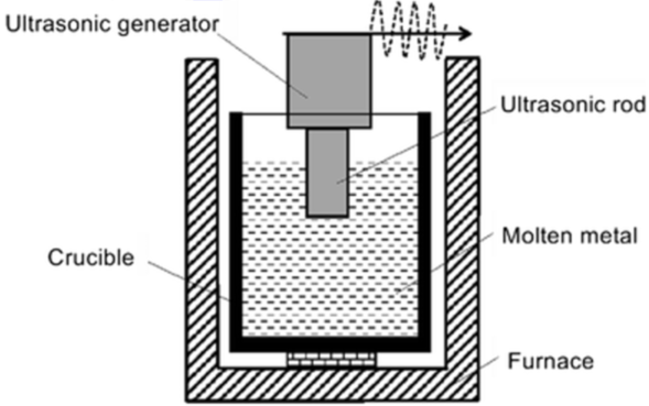

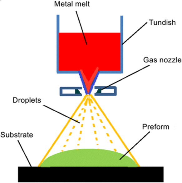
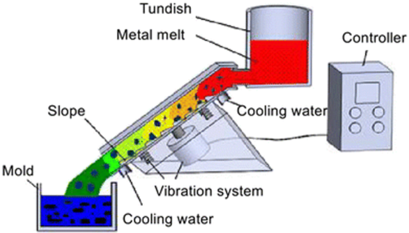
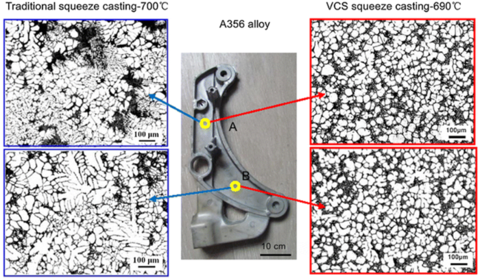
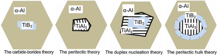
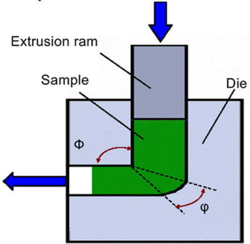
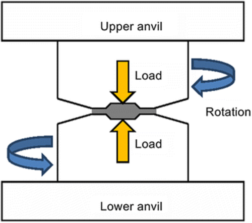
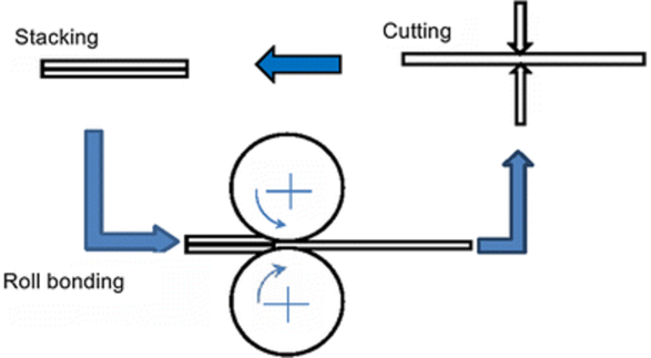


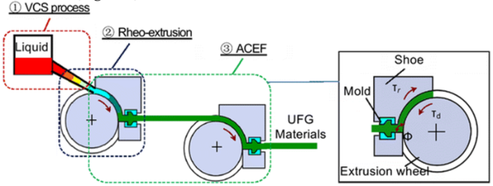
