Search for articles:
Ting-Ting Zhang , Jun Zhou
Corresponding authors:
Received: 2017-07-13
Revised: 2017-07-13
Online: 2017-07-13
Copyright: 2017 Editorial board of Acta Metallurgica Sinica(English Letters) Copyright reserved, Editorial board of Acta Metallurgica Sinica(English Letters)
More
Abstract
In this study, 6061 aluminum alloy and AZ31B magnesium alloy composite plate was fabricated through explosive welding. Molecular dynamics (MD) simulations were conducted to investigate atomic diffusion behavior at bonding interface in the Al/Mg composite plate. Corresponding experiments were conducted to validate the simulation results. The results show that diffusion coefficient of Mg atom is larger than that of Al atom and the difference between these two coefficients becomes smaller with increasing collision velocity. The diffusion coefficient was found to depend on collision velocity and angle. It increases linearly with collision velocity when the collision angle is maintained constant at 10° and decreases linearly with collision angle when the collision velocity is maintained constantly at 440 m/s. Based on our MD simulation results and Fick’s second law, a mathematical formula to calculate the thickness of diffusion layer was proposed and its validity was verified by relevant experiments. Transmission electron microscopy and energy-dispersive system were also used to investigate the atomic diffusion behavior at the bonding interface in the explosively welded 6061/AZ31B composite plate. The results show that there were obvious Al and Mg atom diffusion at the bonding interface, and the diffusion of magnesium atoms from magnesium alloy plate to aluminum alloy plate occurs much faster than the diffusion of aluminum atoms to the magnesium alloy plate. These findings from the current study can help to optimize the explosive welding process.
Keywords:
Magnesium and magnesium alloys are increasingly used in automotive and aerospace industries due to their low density and high specific strength [1, 2, 3]. However, their poor corrosion resistance and room-temperature ductility significantly limit their further applications [4, 5]. In contrast, aluminum alloy has good corrosion resistance. Hence, composite plates made of Al/Mg alloys can not only prevent the corrosion problem of magnesium alloy, but also possess the good properties of both aluminum and magnesium alloys [6, 7, 8].
The major problem of joining these two dissimilar alloys is the formation of the brittle intermetallic compounds in welded joint if traditional welding methods are applied which results in a great decrease in mechanical properties of the joint [9]. Instead, solid-state welding techniques such as explosive welding can be adopted to join these two dissimilar alloys without the formation of unexpected brittle phases [10]. Using OM and SEM, Yan [11] reported the microstructure of AZ31B/7075 cladding plate fabricated by explosive welding. They found that the thickness of diffusion layer at bonding interface was approximately 3.5 μm. However, formation of the diffusion layer was not studied. Zhang [12] investigated the effect of different annealing conditions on the microstructure and mechanical properties for the explosive-welded AZ31B/AA6061 alloy plates. Through EDS analysis, they found that the thickness of the diffusion layers increased significantly with increasing annealing temperature and time and the bonding strength of the explosively welded cladding plate is tightly related to the formation of the diffusion layer.
Due to the instantaneous and dangerous nature of explosive welding which involves an oblique high-speed collision between two plates [13, 14], it is a technical challenge to predict atomic diffusion and the mechanical properties of welded joint. The atomic diffusion process in diffusion layer during welding is believed to be related to the morphology of the bonding interface and the strength of the joint. Molecular dynamics (MD) simulation has shown its advantages in tracking the movement of atoms and studying the related diffusion phenomena at an atomic level. Chen [15, 16] reported a MD study of the effects of the transverse and longitudinal velocities on atomic diffusion behavior in Cu/Al explosive welding.
In the current study, in order to investigate atomic diffusion behavior at the bonding interface in the explosively welded Al/Mg composite plate, similar MD simulations were conducted. The effects of welding parameters such as collision velocity and angle on diffusion behaviors were further investigated. Based on simulation results and Fick’s second law, mathematical formulas have been proposed to calculate the diffusion layer thickness. Experiments were also conducted to validate the MD simulation results.
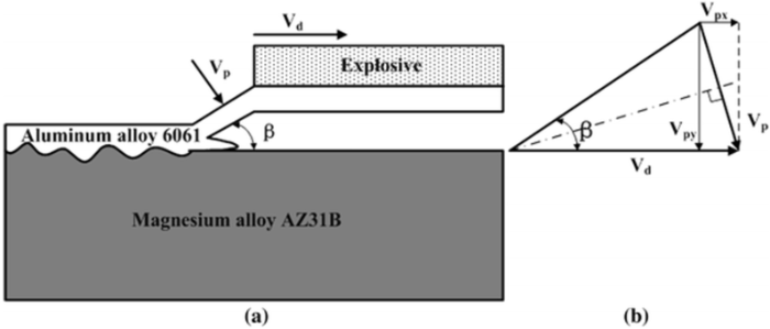
Figure 1a shows a schematic sketch of an explosive welding process. The macroscopic welding process parameters used in the MD simulations are flyer plate velocity Vp and detonation velocity Vd. They should satisfy the following equation when the gap geometry is parallel.
$$V_{\text{p}} = 2V_{\text{d}} \sin \frac{\beta }{2} ,\ \ (1)$$
where β is the dynamic bend angle. Geometrical analysis [17] shows that Vp has two components: Vpx (transverse velocity) and Vpz (longitudinal velocity), as showed in Fig. 1b. They are given as
$$V_{px}=2V_{d}sin^{2}\frac{\beta}{2},\ \ (2)$$
$$V_{py}=2V_{d}sin^{2}\beta , \ \ (3)$$
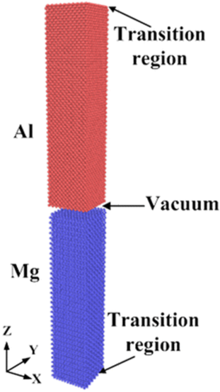
Based on above information, a MD model to simulate the diffusion process in the current explosive welding was developed using LAMMPS [18]. Figure 2 shows the initialization configuration for the MD simulation. As shown, the system consists of a magnesium slab having 18,000 atoms on the top and an aluminum slab having 12,483 atoms on the bottom. These two slabs are placed inside a simulation box with a dimension of 4.05 nm × 4.05 nm × 36.45 nm. The contact surfaces of Mg and Al are (0 0 0 1) and (0 0 1) plane, respectively. Between them, vacuum is used to isolate the slabs’ initial free surfaces. Periodic boundary conditions are implemented in x- and y-direction. At the bottom of Mg slab and on the top of Al slab, three layers of atoms are treated as the transition regions to reduce the influence of high-speed shock waves. The embedded atomic method potential for Mg/Al alloys developed by Mendelev [19] is adopted. The initial velocities of the atoms are assumed to be at Maxwell distribution. The Newton’s second law of motion equation for the atoms is numerically integrated using the leap-frog algorithm with a fixed time step of 1 fs. The system is relaxed at 300 K and zero pressure under a constant pressure-temperature (NPT) ensemble for 300 ps to finish the initialization.
Fig. 1 Schematic of Al/Mg composite plate by explosive welding: a explosive welding process; b geometrical analysis
Fig. 2 Initialization configuration for the MD simulation
In general, collision process during explosive welding has a loading stage and an unloading stage [10, 20]. At the beginning of simulation, the Al slab is given a velocity (Vpx and Vpz) to simulate the oblique collision, while the transition region of Mg slab is fixed. As the Al slab moves toward the Mg slab, the transition region of Al is fixed till the system reaches its minimum length. Then, the system is relaxed for 1000 ps in a micro-canonical (NVE) ensemble to finish the loading stage. Finally, at the equilibrium temperature, the system is relaxed for another 1000 ps in a canonical (NVT) ensemble.
The effects of Vp and β on diffusion behaviors are investigated in our studies. Firstly, β is fixed at 10°, Vp changes from 400 to 480 m/s with an increase in every 10 m/s. Then, Vp is fixed at 440 m/s, and β changes from 2° to 12° with an increase in every 2°. The initial conditions used in simulations are given in Table 1.
Table 1 Initial condition parameters in the simulation
| No. | β (°) | Vp (m/s) | Vpx (m/s) | Vpz (m/s) | Vd (m/s) |
|---|---|---|---|---|---|
| 1 | 10 | 400 | 34.86 | -398.48 | 2294.74 |
| 2 | 10 | 410 | 35.73 | -408.44 | 2352.11 |
| 3 | 10 | 420 | 36.61 | -418.40 | 2409.48 |
| 4 | 10 | 430 | 37.48 | -428.36 | 2466.85 |
| 5 | 10 | 440 | 38.34 | -438.33 | 2524.22 |
| 6 | 10 | 450 | 39.22 | -428.36 | 2581.59 |
| 7 | 10 | 460 | 40.09 | -458.25 | 2638.95 |
| 8 | 10 | 470 | 40.96 | -468.21 | 2696.32 |
| 9 | 10 | 480 | 41.83 | -478.17 | 2753.69 |
| 10 | 2 | 440 | 7.68 | -439.93 | 12,605.7 |
| 11 | 4 | 440 | 15.36 | -439.73 | 6303.82 |
| 12 | 6 | 440 | 23.03 | -439.40 | 4203.61 |
| 13 | 8 | 440 | 30.69 | -438.93 | 3153.83 |
| 14 | 10 | 440 | 38.35 | -438.33 | 2524.22 |
| 15 | 12 | 440 | 45.99 | -437.59 | 2104.69 |
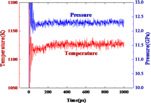
The atomic diffusion behavior was found to be closely related to temperature and pressure [21, 22], so a similar investigation was conducted in this study. Figure 3 shows the temperature and pressure change in system with time during the loading stage when Vp = 440 m/s and β = 10°. As shown, within about 200 ps, system temperature increases dramatically to around 1126 K and system pressure also increases rapidly to about 12.32 GPa. After that, the temperature and pressure reach a dynamic equilibrium state with no further increase. These phenomena can be explained through following discussions of collision and energy conversion processes in the system during welding. At the loading stage, the Al slab possesses a high impact velocity and the transition layer of Mg is stationary. When two slabs begin to collide, the kinetic energy of the Al slab is converted into the internal energy of the system, leading to a dramatic increase in the system temperature. At the same time, due to the decrease in the system volume and the increase in the atomic repulsive force, the system pressure, hence, increases rapidly. The pressure in the collision zone is within a range around dozen GPa. These simulation results agree with the findings in previous studies [10, 20]. It should be noted that, the increase in the system temperature contributes to the activation of both Al and Mg atoms. Meanwhile, the atoms near the interface can achieve an intimate contact under such a high pressure. All these help to produce an adhesion joint between Mg and Al at loading stage.
Fig. 3 Temperature and pressure change in system with time during the loading stage when Vp = 440 m/s and β = 10°
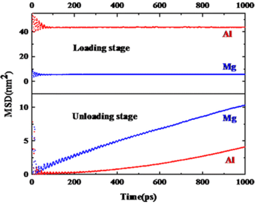
In order to describe the diffusion behaviors of the atoms, mean-squared displacement (MSD) is employed to analyze the motion state of the atoms. Figure 4 shows the MSD curves in z-direction when Vp = 440 m/s and β = 10°. As shown, at loading stage, the MSD of both Mg and Al fluctuates at the beginning and then quickly achieves a steady value around 5.66 and 43.62 nm2, respectively. This indicates that there is no Mg nor Al atom diffusion during loading stage since the interatomic distance between Mg and Al atom is too short to allow Mg and Al atoms to diffuse into each side under high pressure(about 12.32 GPa) though the temperature is high (1126 K). At unloading stage, the MSD of Mg rapidly increases linearly (although with some fluctuations) and reaches about 10.28 nm2 at t = 1000 ps. The MSD of Al begins to increase after about 300 ps and increases linearly afterward and reaches around 4.09 nm2 at t = 1000 ps. This indicates that the Mg atoms near the interface begin to diffuse as soon as the pressure is unloaded and the Al atoms begin to diffuse after about 300 ps. This is because Mg and Al atoms can diffuse into each side when the interatomic distance gets large enough.
Fig. 4 Mean-squared displacement curves in the z-direction during the loading stage and the unloading stage when Vp = 440 m/s, β = 10°
In addition, it should be noted that half of the slope of a MSD curve in z-direction represents the diffusion coefficient. As shown, the slope of the MSD curve of Mg is larger than that of Al at the given velocity, which indicates that the diffusion coefficient of Mg (about 0.00451 nm2/ps) is larger than that of Al (about 0.00278 nm2/ps) under the given velocity. MSD curves at various velocities and angles are obtained, and corresponding diffusion coefficients are calculated.
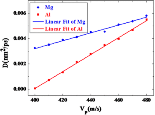
Figure 5 shows the diffusion coefficients of Mg and Al at different collision velocities when β is fixed at 10°. The atoms begin to diffuse when Vp exceeds 400 m/s. The diffusion coefficients of Mg and Al increase linearly from 0.00325 and 0.00006 to 0.00581 and 0.0055 nm2/ps, respectively, and reach their maximums at 480 m/s. It can be found that the diffusion coefficient of Mg is larger than that of Al at the given velocity. The difference in diffusion coefficient between Mg and Al is getting smaller with increasing Vp. These phenomena are related to the structural change in Al side, which will be explained in 3.3.
Fig. 5 Diffusion coefficients of Al and Mg at different collision velocities when β = 10°
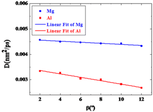
Figure 6 shows the diffusion coefficients of Al and Mg at different collision angles when Vp is fixed at 440 m/s. As shown, the diffusion coefficient of Mg is larger than that of Al. With the increase in collision angle, the diffusion coefficients of both Mg and Al decrease linearly from 0.00456 and 0.00334 to 0.00432 and 0.00267 nm2/ps, respectively. It should be noted that the increase in the collision angle leads to the increase in longitudinal velocity and the decrease in transverse velocity, which indicate that the effect of the longitudinal velocity on diffusion coefficient is greater than that of the transverse velocity. In addition, comparing Fig. 6 with Fig. 5, we can find the influence of the collision velocity on the diffusion coefficient is higher than that of collision angle.
Fig. 6 Diffusion coefficients of Al and Mg at different collision angles when Vp = 440 m/s
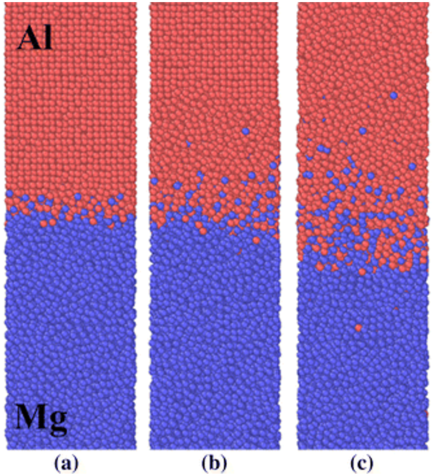
The atomic diffusion behavior varies with flyer plate velocity. Figure 7 shows configurations at different velocities obtained 300 ps after loading stage starts when β are fixed at 10°. For Vp = 400 m/s (as displayed in Fig. 7a), only a small number of Mg atoms have diffused into the Al side. In this case, there is no obvious structural change in Al side and Mg side exhibits disordered structure. This is because Mg atom has a smaller radius than Al atom. Obviously, it is easier for smaller (Mg) atoms to diffuse into a region of relatively larger (Al) atoms. For Vp = 440 m/s (shown in Fig. 7b), the Al side near the interface shows an amorphous structural order and Mg and Al atoms diffuse into each side and form an interfacial region. For Vp = 480 m/s (as shown in Fig. 7c), the entire Al side exhibits an amorphous structure. More Mg and Al atoms diffuse into each side and the interfacial region gets larger. This is because when the velocity is small, Al remains the fcc structure and only small amount of Al-Al bonds near the interface is broken. As the velocity increases, more Al-Al bonds are broken, which contributes to the diffusion of more Al atoms. This explains why the diffusion coefficient of Mg is larger than that of Al at lower velocity, and the difference becomes smaller when the velocity increases as mentioned before.
Fig. 7 Configurations of the cross section when β = 10°, Vp = a 400 m/s, b 440 m/s, c 480 m/s at 300 ps after loading stage begins
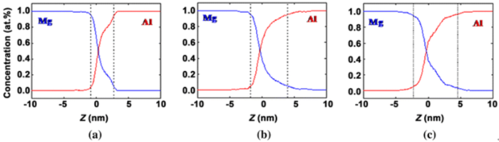
The interfacial region is noticed to get larger with increasing velocity. The thickness of the interfacial region can be calculated by extracting the coordinate information of Mg and Al atoms from the LAMMPS dump files. The concentrations of Al and Mg atoms along z-direction for above three cases shown in Fig. 7 are calculated, and results are given in Fig. 8. Interfacial region is defined as a region where the concentrations of Mg and Al atoms are both over 5%. Thus, the thickness of interfacial region can be determined from these concentration curves. As shown in Fig. 8, when Vp = 400 m/s, the thickness of the interfacial region is approximately 3.57 nm. With the increase in the collision velocity, the thickness of the interfacial region increases to 5.69 and 6.95 nm for Vp = 440 and 480 m/s, respectively. In addition, it can be found that the diffusion thickness of Mg is larger than that of Al, which is also a proof that the diffusion coefficient of Mg is larger than that of Al.
Fig. 8 Concentrations of Al and Mg atoms along the z-direction when β = 10°, Vp = a 400 m/s, b 440 m/s, c 480 m/s after 1000 ps in loading stage
In order to predict the actual diffusion layer thickness in the Al/Mg explosive welding joint which has a direct effect on the mechanical properties of the joint, we consider the diffusion process based on the classical diffusion theory. Since temperature remains unchanged during unloading stage, the system can be treated as an isothermal system. The diffusion processes of Mg and Al can be described using Fick’s second law [23]:
$$\frac{\partial n}{\partial t} = D\nabla^{2} n ,\ \ (4)$$
where n is the atom concentration, t is time, and D is the diffusion coefficient. Here we consider one-dimensional diffusion in z-direction. For a one-dimensional diffusion process in solid, the solution of Eq. (4) is given as
$$ n(x,t) = \frac{1}{2}\left[ {1 - {\rm erf}\left( {\frac{z}{{2\sqrt {Dt} }}} \right)} \right] ,\ \ (5)$$
where erf is the complementary error function. z is the diffusion distance along z-direction. It is reported that the diffusion distance is directly proportional to (Dt)1/2 [24]. Thus, the diffusion thickness L can be calculated by:
$$ L = \sum\limits_{{i = {\text{Mg, Al}}}} {k\sqrt {D_{i} t} } ,\ \ (6)$$
where Di is the diffusion coefficients of Mg and Al. k is a constant which depends on the diffusion condition and can be obtained through the simulation results. Using the case of Vp = 440 m/s, β = 10° as an example, the thickness of the interfacial region as a function of time during unloading stage is shown in Fig. 9. The thickness of the interfacial region is found to increase with time. The data are curve fitted with a form of $y=k\sqrt{t}$, and the fitted equation is $y=0.1787\sqrt{t}$. Based on the simulation results, the diffusion coefficients of Mg and Al are 0.00451 and 0.00278 nm2/ps, respectively (as shown in Fig. 5). Thus, k = 1.4906. Then, Eq. (6) can be expressed as:
$$ L = \sum\limits_{{i = {\text{Mg, Al}}}} {1.4906\sqrt {D_{i} t} } ,\ \ (7)$$
Yan et al. [25] and Chen et al. [15] found that unloading stage could last for 5-10 μs in an actual explosive welding process. In addition, the system can be treated as an isothermal system during unloading stage. The diffusion coefficient remains constant under this condition. Thus, we can predict the diffusion layer thickness using Eq. (7). The mathematic formulas for calculating the diffusion thickness for different velocities when β is fixed at 10° can be obtained using the same approach and are given in Table 2.
Fig. 9 Thickness of the interfacial region as a function of time when Vp = 400 m/s, β = 10° in the unloading stage
Table 2 Prediction equations at different velocities when $\beta$ is fixed at 10°
| Velocity (m/s) | DMg (nm2/ps) | DAl (nm2/ps) | Fitted equation (nm) | Prediction equation (nm) |
|---|---|---|---|---|
| 400 | 0.00375 | 0.00006 | \(y=0.1183 \sqrt{t}\) | \(L =\sum\limits_{{i={Mg, Al}}} {1.7149\sqrt {D_{i}t}}\) |
| 410 | 0.00351 | 0.00071 | \(y=0.1451t\sqrt{t}\) | \(L =\sum\limits_{{i={Mg, Al}}} {1.6893\sqrt {D_{i}t}}\) |
| 420 | 0.0039 | 0.00132 | \(y=0.1542t\sqrt{t}\) | \(L =\sum\limits_{{i={Mg, Al}}} {1.5610\sqrt {D_{i}t}}\) |
| 430 | 0.00412 | 0.00215 | \(y=0.1644t\sqrt{t}\) | \(L =\sum\limits_{{i={Mg, Al}}} {1.4870\sqrt {D_{i}t}}\) |
| 440 | 0.00451 | 0.00278 | \(y=0.1787t\sqrt{t}\) | \(L =\sum\limits_{{i={Mg, Al}}} {1.4906\sqrt {D_{i}t}}\) |
| 450 | 0.00454 | 0.00348 | \(y=0.1921 \sqrt{t}\) | \(L =\sum\limits_{{i={Mg, Al}}} {1.5201\sqrt {D_{i}t}}\) |
| 460 | 0.0051 | 0.00398 | \(y=0.1922 \sqrt{t}\) | \(L =\sum\limits_{{i={Mg, Al}}} {1.4810\sqrt {D_{i}t}}\) |
| 470 | 0.00537 | 0.00468 | \(y=0.2078 \sqrt{t}\) | \(L =\sum\limits_{{i={Mg, Al}}} {1.4666\sqrt {D_{i}t}}\) |
| 480 | 0.00581 | 0.00550 | \(y=0.2221 \sqrt{t}\) | \(L =\sum\limits_{{i={Mg, Al}}} {1.4769\sqrt {D_{i}t}}\) |
Relevant experiments were conducted to validate the simulation results. Figure 10 shows the schematic sketch of an experimental setup for the explosive welding of 6061 Al/AZ31B Mg alloy. A parallel setup is adopted, and AZ31B alloy is as base plate and 6061 alloy is as flyer plate. The dimensions of AZ31B and 6061 are 300 mm × 300 mm × 15 mm and 350 mm × 350 mm × 3 mm, respectively. The standoff distance between them is 3 mm. The explosive is AMATOL power with a height of 15 mm to generate a detonation velocity approximately equal to 2500 m/s.
Fig. 10 Schematic sketch of an experimental setup for the explosive welding of 6061 Al/AZ31B Mg alloy
The surface and cross-sectional morphologies of the 6061/AZ31B cladding plate after explosive welding are given in Fig. 11. As shown, 6061 aluminum alloy and AZ31B magnesium alloy composite plate has been successfully fabricated. The 6061/AZ31B composite plate has a good appearance. The plate was non-destructively examined through an ultrasonic test, and no significant defects (such as non-bonding or pores defects) were found.
Fig. 11 Surface and cross-sectional morphologies of the 6061/AZ31B cladding plate after explosive welding
The micro-morphology is further studied using scanning electron microscopy (SEM), transmission electron microscope (TEM), and the energy-dispersive spectroscope (EDS). Figure 12a shows the SEM micrograph of the AZ31B/6061 composite plate interface after explosive welding. It can be found that the interface was bonded together very well. A wavy morphology appeared at the bonding interface. Figure 12b shows the EDS line scan across the bonding interface. It is clear that there is a thin diffusion layer at the bonding interface. The diffusion layer is indicated by the two dash lines. The thickness of the diffusion layer is approximately 0.524 μm.
Fig. 12 SEM micrograph a, EDS line scan b of the AZ31B/6061 composite plate interface after explosive welding
The simulation parameters are Vp = 440 m/s, β = 10°, and Vd = 2524.22 m/s to match the experimental velocity used. The thickness of the diffusion layer was calculated by using Eq. (7) between 0.399 μm at t = 5 μs and 0.565 μm at t = 10 μs. The diffusion layer thickness (0.524 μm) is in line with the simulation result (0.399-0.565 μm). Thus, the mathematical formula proposed to calculate the diffusion layer thickness is validated successfully by the experimental results.
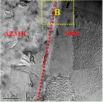
The TEM image showing the bonding interface between the AZ31B magnesium alloy and 6061 aluminum alloy plate is given in Fig. 13. A good fault-free bonding interface is found. At AZ31B alloy plate side adjacent to the interface, fine equiaxed gains were found due to dynamic recrystallization. Since the location adjacent to the interface has the highest energy concentration [26, 27], based on the dynamic recrystallized condition, the equiaxed grains are easy to form at the deformed structure position. The aluminum alloy plate side near the interface has typical polygonal appearance grains. This difference in microstructure morphology is due to the different crystal structures of Al alloy and Mg alloy. 6061 alloy with body-centered cubic (bcc) crystal structure has excellent plastic deformation capability, while the AZ31B alloy has bad plasticity in ambient temperature because of its hexagonal close-packed (hcp) crystal structure. Due to this difference in crystal structure, the stacking fault energy of Mg alloy is lower than that of Al alloy, and there are only 3 slip systems in Mg alloy, but 48 slip systems in Al alloy [28]. Thus, the recrystallization is much easier in Al alloy than in Mg alloy.
Fig. 13 TEM image of the bonding interface after explosive welding
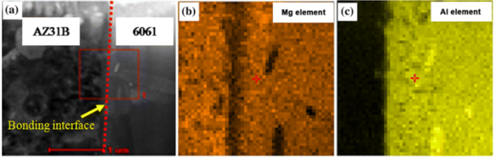
Figure 14 shows the EDS testing results of the zone at the interface boxed in Fig. 13. As shown, diffusions of Al and Mg elements can be found obviously at the bonding interface. Also, at the bonding interface, more magnesium atoms diffuse into the aluminum alloy plate than the diffusion of aluminum atoms into the magnesium plate, which is consistent with above simulation results.
Fig. 14 EDS testing results of the zone at the interface boxed in
By using molecular dynamic simulation, atomic diffusion behaviors at bonding interface in Al/Mg explosive welding were studied. Conclusions are drawn as follows:
1. The atomic diffusions mainly take place during the unloading stage in Al/Mg explosive welding when high temperature and pressure occur instantaneously. The diffusion coefficient of Mg is larger than that of Al, and the difference is getting smaller with increasing collision velocity.
2. The diffusion coefficient depends on the collision velocity and the angle. It is found to increase linearly with the collision velocity when the collision angle is maintained at 10° and decrease linearly with the collision angle when the collision velocity is set at 400 m/s. The diffusion coefficient is affected more by the collision velocity than by collision angle.
3. The thickness of interfacial region increases with increasing collision velocity, and it can be calculated by using a validated proposed mathematical formula.
4. TEM and EDS results show that good bonding was achieved in the explosively welded Al/Mg composite plate and the diffusions of Al and Mg atoms were found clearly at the bonding interface.
This work was financially supported by the National Natural Science Foundation of China (No. 51375328).
The authors have declared that no competing interests exist.

 WeChat
/
| 〈 |
|
〉 |