


A Comparison Study of Wear and Fretting Fatigue Behavior Between Cr-alloyed Layer and Cr-Ti Solid-solution Layer
[Shou-Ming Yu , Dao-Xin Liu, Xiao-Hua Zhang, Cheng-Song Liu]
, Dao-Xin Liu, Xiao-Hua Zhang, Cheng-Song Liu]
|
|


This work reported a comparison between the wear and fretting fatigue (FF) behaviors of a Cr-alloyed layer and a Cr-Ti solid-solution layer. The hardness and toughness of both layers were evaluated to support this comparison. The results showed that the Cr-alloyed layer had high surface hardness but poor toughness, while the Cr-Ti solid-solution layer had excellent toughness but low hardness. The FF properties of the modified Ti6Al4V alloy depended on the trade-off between two factors: wear resistance and fatigue resistance. Although the Cr-alloyed layer could effectively resist the wear in fretting areas, its poor toughness caused the fatigue resistance to drop sharply and hence led to a premature failure in FF test. Due to the relatively good fatigue resistance, the Cr-Ti solid-solution layer had slightly higher FF life than that of the Cr-alloyed layer; however, its low hardness resulted in severe wear in correspondence with the fretting area and thus a failure to improve the FF properties of Ti6Al4V alloy. When combined with shot peening post-treatment, the FF life of both layers increased by about three times compared to that of the Ti6Al4V alloy. A further study showed that the poor toughness or low hardness still exerted negative influence on combination-treated samples.
Ti alloys are widely used in the aerospace, marine, automotive and biomedical industries due to their outstanding properties such as high specific strength, exceptional corrosion resistance and excellent biocompatibility [1, 2]. However, their applications have been limited due to their poor tribological properties and susceptibility to fretting fatigue (FF) damage [3, 4, 5]. To solve the problem of FF damage, the anti-wear and anti-fatigue properties of Ti alloys should be simultaneously improved. Surface hardening treatments can improve the wear resistance remarkably [6, 7, 8] but often reduce the fatigue resistance, owing to the low toughness of the hardened surface [9, 10, 11, 12], making it difficult to solve the anti-wear and anti-fatigue issues through a single surface treatment.
A promising approach may be represented by a combined surface treatment, in which both alloying and surface deformation are carried out. Tsuji et al. [10] and Li et al. [12] induced residual compressive stress via shot peening to recover the previously reduced fatigue properties of Ti alloys treated through plasma carburizing or thermal oxidation. However, these hard compound layers (i.e., TiC or TiO2) were prone to crack or flake when combined with a surface deformation treatment, due to their poor toughness. This would inevitably have a negative effect on FF properties. Our previous work [13] showed that the Cr-alloyed layer had high hardness but poor toughness and therefore would have a high resistance to wear, but low fatigue resistance, with a high risk of cracking or flaking during the shot peening process. On the other hand, if the top sub-layers of the Cr-alloyed layer were removed, the remaining sub-layer, i.e., Cr-Ti solid-solution layer, had excellent toughness but low hardness. The ductile Cr-Ti solid-solution layer had better fatigue resistance and could obtain higher residual compressive stress than that of the hard Cr-alloyed layer after shot peening treatment. Thus, the Cr-Ti solid-solution layer that underwent the shot peening treatment had much better plain fatigue properties than that of the shot peened Cr-alloyed layer. The low hardness of the Cr-Ti solid-solution layer may, however, lead to severe wear in the FF process. Therefore, it would be valuable to study the FF behaviors of the hard Cr-alloyed layer and the ductile Cr-Ti solid-solution layer, and especially the behaviors of both layers combined with shot peening post-treatment.
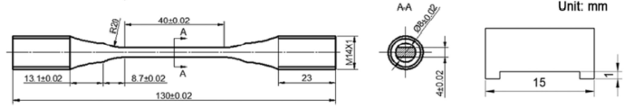
Hot-rolled and annealed Ti6Al4V alloy bars were supplied by Treasure Titanium Group Co., Ltd. This alloy is an α + β phase and had a nominal chemical composition of 6.7% Al, 4.2% V, 0.1% Fe, 0.03% C, 0.015% N, 0.03% H, 0.14% O and balance Ti [14]. The ultimate and yield strengths at room temperature were 1080 and 1010 MPa, respectively. Eight-millimeter-thick disk samples were cut from a 30-mm-diameter bar and ground using 1200 grade SiC sandpapers. The characteristics and wear behavior of these samples were determined after plasma chromizing. The FF specimens were cut from a 16-mm-diameter bar and machined to a geometry as shown in Fig. 1.
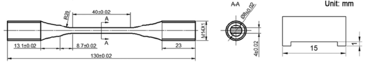 | Fig. 1 Schematic drawing of Ti6Al4V alloy fretting fatigue specimen and Ti6Al4V alloy fretting pad |
Plasma chromizing treatment was carried out using a double-glow plasma surface-alloying device, and the preparation process of the Cr-alloyed layer was reported in [13]. The sputtering targets were two commercially pure 180 mm × 150 mm × 6 mm Cr plates. Plasma chromizing was conducted at a target bias voltage of -850 V, a substrate bias voltage of -450 V and a substrate temperature of 800 ° C, with a 32 mm distance between the target and the substrate. The treatment lasted 4 h. Throughout the process, the working pressure of Ar gas was 40 Pa.
The Cr-Ti solid-solution layer was one of the sub-layers of the Cr-alloyed layer. After the removal of the top sub-layers of the Cr-alloyed layer, using HCl solution at 38 ° C, the remaining sample consisted only of a Cr-Ti solid-solution layer.
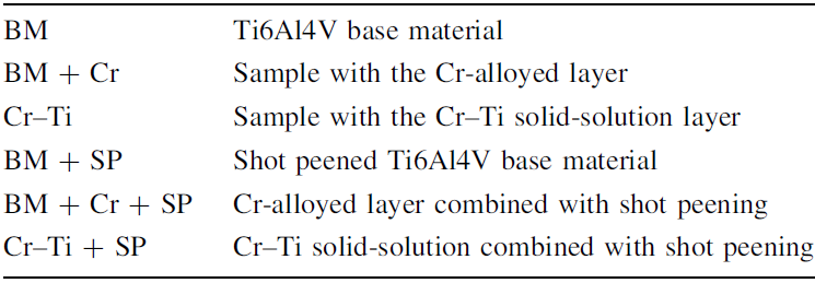
The shot peening process was performed by using an automatic air pressure-type shot peening machine under an Almen intensity of 0.25 A and a coverage of 150%; zirconia ceramics media were used as the shot particles, and the process was performed at a shot angle of 90° . The samples investigated in this work are listed in Table 1.
| Table 1 Samples used in the experiments |
The cross-sectional morphology of the Cr-alloyed layer was examined by a scanning electron microscopy (SEM). The hardness of the cross section was evaluated using a micro-hardness tester, equipped with a Knoop diamond indenter, with a 50 g load and a dwell time of 20 s. The toughness of the Cr-alloyed and Cr-Ti solid-solution layers was determined at a maximum load of 150 N and a loading time of 30 s, using a static indention tester equipped with a Rockwell indenter (cone angle: 120° ; tip radius: 0.2 mm). The residual stress was evaluated via XRD using a sin2ψ method with Ti-K radiation at the {110} plane of the hexagonal α Ti phase or the {200} plane of the Cr phase. The full width at half maximum method was used to determine the peak position. The XRD scans were performed over 2θ ranges of 134° -148° and 140° -154° for the α Ti and Cr phases, respectively. The top layers of the Cr-alloyed layer were removed using HCl solution at 38 ° C.
The wear test was carried out with a ball-on-disk tester under a 5 N load at room temperature. The counterpart was a GCr15 steel sphere with 5 mm in diameter (701 HK0.05). The wear trace diameter was 8 mm. The sliding velocity was 224 r/min, and the sliding time was 26.7 min, yielding a total sliding distance of 150 m. For each type of the sample, three tests were carried out under the same conditions. The volume loss due to wear was evaluated by a profile meter. Morphologies of the worn surface were examined by the SEM having energy dispersive spectroscopy (EDS) capabilities.
A homemade device was used to conduct the FF tests in a hydraulic servo controlled fatigue testing machine. The fatigue loading was set to pull-pull mode, and the maximum cyclic stress force was 550 MPa in sinusoidal form at 40 Hz and a stress ratio of 0.1. The contact state between the FF specimen and the Ti6Al4V alloy pad was flat surface to flat surface, with a rectangular contact area of 2 mm × 6 mm (Fig. 1). The contact zone stress was controlled at 85 MPa by a stress ring. The FF life was taken as the average of the values measured for the five specimens. Tests were carried out at room temperature.
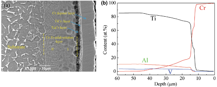
Figure 2 shows the cross-sectional structure and composition depth profile of the Cr-alloyed layer. The previous work [13, 15] reported that the microstructure of the Cr-alloyed layer was mainly composed of a Cr deposit layer, a TiCr2 layer, a Ti4Cr layer and a Cr-Ti solid-solution layer. To observe the microstructure, the cross section of the Cr-alloyed layer was etched in a mixed acid solution of HNO3 and HF. The Cr-alloyed layer was actually compact and continuous, while the holes in the Ti4Cr layer resulted from the etching action of the mixed acid solution [13]. The Cr-Ti solid-solution layer contains two distinct microstructures[15]: region I consists of (α Ti, Cr) and Ti4Cr phases; region II consists of (α Ti, Cr), Ti4Cr and (β Ti, V) phases and presents a fine (α Ti, Cr) + (β Ti, V) lamellar structure.
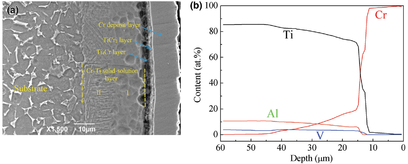 | Fig. 2 Cross-sectional structure a and composition depth profile b of the Cr-alloyed layer |
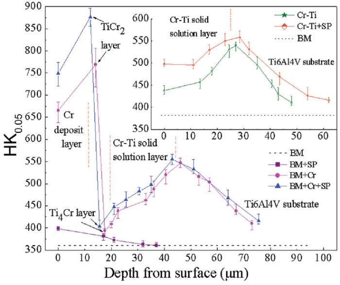
Figure 3 shows the cross-sectional micro-hardness measurements of various surface-treated samples. It may be seen that the surface hardness of the Cr-alloyed layer reached 670 HK, while the surface hardness of the Cr-Ti solid-solution layer was only 430 HK. The TiCr2 layer displayed the maximum hardness, while the Ti4Cr layer had the minimum hardness among the four sub-layers of the Cr-alloyed layer. In contrast to the expected outcome, the hardness of the Cr-Ti solid-solution layer showed an increase tendency with decreasing Cr content. This was mainly attributed to the precipitation of the soft Ti4Cr phase [15]. The amount of Ti4Cr precipitate declined with decreasing Cr content, and thus, the hardness gradually increased.
 | Fig. 3 Cross-sectional hardness profiles of various surface-treated samples |
Shot peening treatment can induce a certain hardening on the surface layer of the treated samples. The increase in surface hardness of several samples may be noticed from Fig. 3. After shot peening, the surface hardness of the Cr-Ti solid-solution layer was increased to about 500 HK and was higher than that of the BM + SP sample about 400 HK).
Figure 4 compares the toughness of the Cr-alloyed layer and the Cr-Ti solid-solution layer. It can be seen that the Cr-alloyed layer cracked when the static load went up to 70 N (Fig. 4a). A further increase in the static load to 150 N caused the formation of a number of cracks on the surface of the Cr-alloyed layer (Fig. 4b), indicating that the Cr-alloyed layer had very poor toughness. As shown in Fig. 4c, however, the problem of a low toughness may be significantly improved through the shot peening post-treatment. The residual compressive stress induced by shot peening can inhibit crack initiation and propagation, so only a small number of cracks appeared. Figure 4d shows that there are no detectable cracks on the surface of the Cr-Ti solid-solution layer under a static load of 150 N. This indicates the Cr-Ti solid-solution layer had excellent toughness.
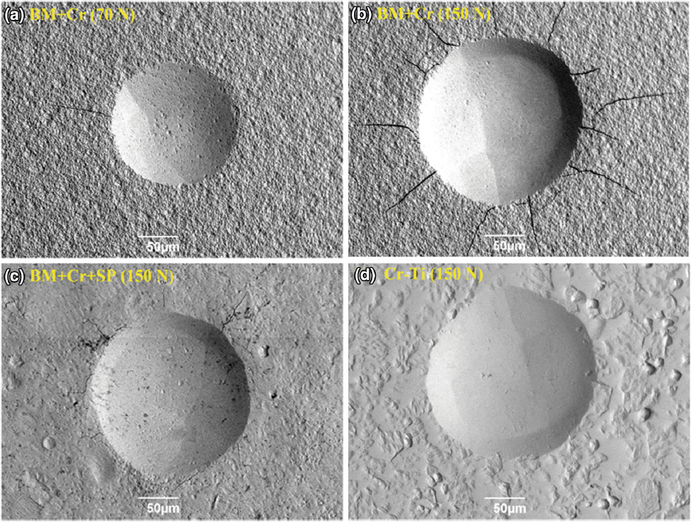 | Fig. 4 BSE images of the samples tested by static indentation at a load of 70 N or 150 N |
The friction coefficients as a function of sliding time for the Ti6Al4V base material and various surface-treated samples are shown in Fig. 5. In the stable stage, the friction coefficients of the Cr-alloyed layer and Cr-Ti solid-solution layer are slightly lower than those of the Ti6Al4V base material. This indicates that neither the Cr-alloyed nor Cr-Ti solid-solution layer has a significant friction-reduction effect against GCr15 steel. After shot peening, the friction coefficients of the Ti6Al4V base material and the Cr-Ti solid-solution layer increased to some extent. This may be related to the changes in the surface roughness. It also can be seen that the friction coefficients of the Cr-alloyed layer and the shot peened Cr-alloyed layer dropped sharply at around 8 and 12 min, respectively. This is caused by the formation of a tribo-oxide layer.
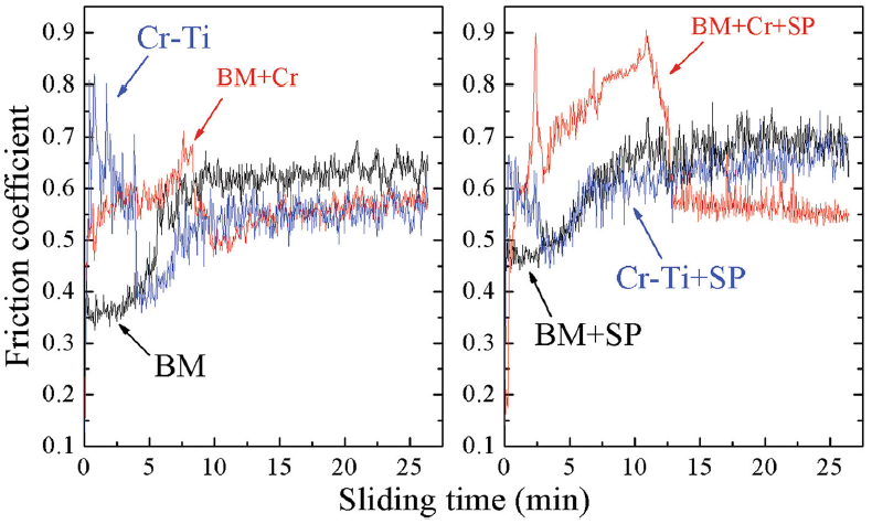 | Fig. 5 Variations in the friction coefficients of Ti6Al4V base material and various surface-treated samples with the function of sliding time |
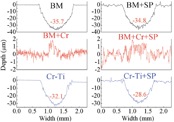
Figure 6 shows the profiles of the wear tracks of Ti6Al4V and various surface-treated samples. These profiles directly reflect the wear volume loss of each sample. It is clear that the Cr-alloyed layer has almost no wear volume loss, and the material transfer may occur on the friction surface. The shot peened Cr-alloyed layer has a similar behavior. The Ti6Al4V base material was seriously worn and the maximum depth of the wear trace reached around 35.7 μ m, as shown in Fig. 6. Moreover, the existence of the Cr-Ti solid-solution layer slightly increases the wear resistance of Ti6Al4V alloy; therefore, its wear trace depth reached 32.1 μ m which was only slightly lower than that of the Ti6Al4V base material (Fig. 6). Similarly, after the shot peening treatment, the wear resistances of the samples were also increased. Compared with the BM and BM + SP samples, the material subjected to Cr-Ti solid-solution and then shot peening could slightly increase the wear resistance (Fig. 6), because of increasing the surface hardness substantially.
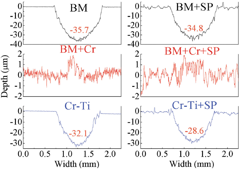 | Fig. 6 Profiles of the wear tracks of Ti6Al4V base material and various surface-treated samples |
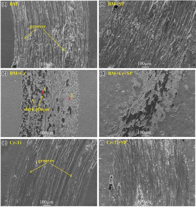
The worn surfaces morphologies of the different samples are shown in Fig. 7. Two main kinds of the morphologies were distinguishable: In the first case, plastic deformation and the grooves along the sliding direction were observed (Fig. 7a, b, e, f) and in the second case, some “ dark plaque” -like (Fig. 7c, d) are visible.
 | Fig. 7 Worn surface morphologies of Ti6Al4V base material and various surface-treated samples |
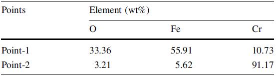
The first kind of morphology was the result of squashing and plowing by the counter-face. The hardness of GCr15 steel was much higher than those of Ti6Al4V and of the Cr-Ti solid-solution layer. The hard asperities of the counter-face may cause the formation of the grooves along sliding direction through a plowing action [16]. Dark wear debris on these wear tracks were observed after wear tests, indicating that the wear debris were crushed to fine particles and underwent oxidation under ambient condition, which could aggravate the abrasion wear [17, 18]. Therefore, abrasive wear was the predominant mechanism for Ti6Al4V and Cr-Ti solid-solution layer. The BM + SP and Cr-Ti + SP samples shared the same wear mechanism. As for the second kind of morphology, EDS analysis showed that the dark plaque (Point-1) observed was an iron- and oxygen-rich area (Table 2), indicating that the material transfers from GCr15 to the Cr-alloyed layer. Owing to high chemical affinity between Cr-alloyed layer and GCr15 steel counterpart, cold welding or adhesion was prone to occur between the friction pairs [19]. Hence, the wear modes of Cr-alloyed layer and shot peened Cr-alloyed layer were mainly the adhesive transfer of counter-body material.
| Table 2 EDS analysis of the Cr-alloyed layer worn surface against GCr15 steel |
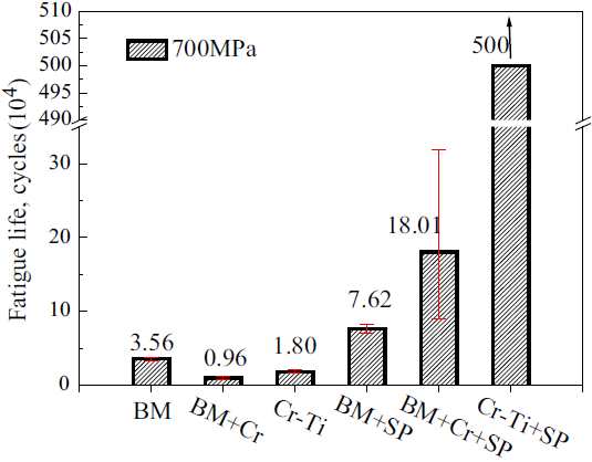
Figure 8 shows the rotating-bending fatigue life of various surface-treated samples under a load of 700 MPa. The previous study [13] reported the combined effects on the plain fatigue (PF) properties of the Ti6Al4V alloy of the Cr-alloyed and Cr-Ti solid-solution layers with shot peening. Compared to the Cr-Ti sample, the BM + Cr sample had a lower fatigue life. This was mainly because the Cr-alloyed layer had poor toughness and thus the crack initiated easily from the surface. Also many cracks initiated from the interfaces between adjacent sub-layers (Cr deposit layer, TiCr2 layer and Ti4Cr layer) in the Cr-alloyed layer, as a consequence of the significant differences in their elastic moduli and hardness. The ductile Cr-Ti solid-solution layer was also ineffective in improving the fatigue properties of the Ti6Al4V alloy. This is because the high temperature reached during the plasma chromizing process may change the microstructure of the core material. In addition, the Cr-Ti solid-solution layer had a low hardness and strength, indicating a low resistance to fatigue crack initiation. Crack initiation is closely related to dislocation movements under alternating shear stresses; the higher the strength of a material is, the less the possibility of dislocation movement is [12].
 | Fig. 8 Plain fatigue life of Ti6Al4V base material and various surface-treated samples at a stress of 700 MPa |
When combined with shot peening post-treatment, both the Cr-alloyed and the Cr-Ti solid-solution layers can obviously increase the fatigue life of the Ti6Al4V alloy (Fig. 8). However, the fatigue life of the Cr-Ti + SP sample was much higher than the BM + Cr + SP sample. This is mainly because shot peening induced a high residual compressive stress in the surface layer of the Cr-Ti solid-solution layer as shown in Fig. 9. Shot peening also improved the toughness of the Cr-alloyed layer (Fig. 4), which was conducive to improve fatigue properties; however, during the shot peening process, the repeated impacts of shot particles may lead to cracking or flaking of the Cr-alloyed layer. It is thus clear that the poor toughness played a negative effect when the Cr-alloyed layer was combined with shot peening post-treatment.
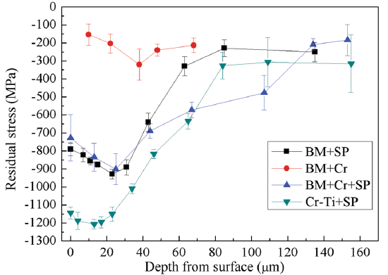 | Fig. 9 Residual stress versus depth profile of various surface-treated samples |
Yu et al. [13]showed that the fatigue life of the BM + Cr + SP sample was higher than that of the BM + SP sample. This was attributed to a higher cross-sectional hardness (Fig. 3) and the distribution of residual compressive stresses over greater depths (Fig. 9). High residual compressive stress could inhibit crack initiation and delay crack propagation and thus prolong the fatigue life [10, 12, 17]. A comparison between the Ti6Al4V base material and the Cr-Ti sample reveals that Cr doping in Ti changed the chemical composition, microstructure and hardness of the surface layer. Thus, the residual compressive stress of the Cr-Ti sample differed from that of the base material.
3.4.1 Fretting Fatigue Test Results
Figure 10 compares the fretting fatigue life of various surface-treated samples at a maximum fatigue load of 550 MPa and a contact stress of 85 MPa. The FF life of the BM + Cr sample was lower than that of the Cr-Ti sample (Fig. 10), in accordance with the result found for the PF (Fig. 8). On the other hand, the FF life of Cr-Ti + SP sample was close to the BM + Cr + SP sample, contrary to the case of PF. This is due to the trade-off between two factors: wear resistance and fatigue resistance. The hard Cr-alloyed layer was beneficial to wear resistance but harmful to fatigue resistance. On the contrary, the ductile Cr-Ti solid-solution layer increased fatigue resistance but reduced wear resistance. The FF lives of the BM + Cr + SP and Cr-Ti + SP samples were slightly higher than that of the BM + SP sample. This slight increase in FF life obtained with the combined treatment is unsatisfactory; therefore, it is necessary to clarify the factors that limited further improvement in FF properties.
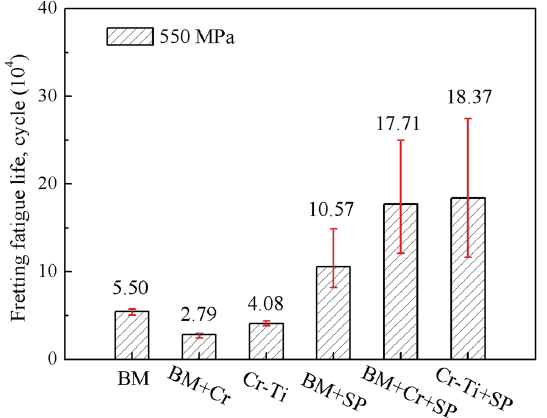 | Fig. 10 Fretting fatigue life of Ti6Al4V base material and various surface-treated samples |
3.4.2 Effects of the Cr-alloyed and Cr-Ti Solid-solution Layers on the Fretting Fatigue Behavior of Ti6Al4V Alloy
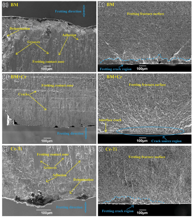
Figure 11 shows the morphologies of the fretting contact zones and FF fracture surfaces of the BM, BM + Cr and Cr-Ti samples. The samples of the fretting contact zones of BM and Cr-Ti were seriously worn and presented obvious adhesion, local delamination and shallow grooves along the fretting direction, as shown in Fig. 11a, e. When the FF sample (i.e., BM or Cr-Ti sample) was in contact with the Ti6Al4V alloy fretting pad, the main damage in fretting contact zone was to the adhesive wear. The adhesive material presented on FF samples (Fig. 11a, e) transformed to debris due to the intense friction between the FF sample and fretting pad. This fretting debris may overflow due to vibration, or lead to the shallow grooves through the smearing actions. As the fretting process continued, the surface morphologies of the fretting contact zones became coarser, leading to stress concentration. Stress concentration could promote the initiation of the micro-cracks [6, 20]. Some micro-cracks on the subsurface gradually extended to the free surface, resulting in the patch delamination in the fretting contact zones of BM and Cr-Ti samples. More importantly, some micro-cracks initiated from the fretting contact zones expanded to the inner material under the tangential force and fatigue stress [12, 21]. The fretting cracks initiated in a large region rather than a point, in the case of PF. This is shown in Fig. 11b, f. This may be because the stress concentration points shifted frequently with the changes in surface morphologies in the fretting area.
 | Fig. 11 Morphologies of the fretting contact zones a, c, e and fretting fatigue fracture surfaces b, d, f of the Ti6Al4V base material a, b, the sample with Cr-alloyed layer c, d and the sample with Cr-Ti solid-solution layer e, f |
The fretting contact zone of the BM + Cr sample showed almost no signs of wear (Fig. 11c); however, many cracks perpendicular to the longitudinal direction were initiated from the Cr-alloyed layer surface because of its poor toughness. Once the cracks initiated, they immediately extended to the inner part of the BM + Cr sample and resulted in early fatigue fracture (Fig. 11d). The interface crack was also observed in Cr-alloyed layer. It is clear that before the fretting wear led to damage in the contact zone, the BM + Cr sample had already fractured due to the low fatigue resistance caused by the poor toughness of the Cr-alloyed layer.
Although the hard Cr-alloyed layer could effectively resist the wear during the FF process, the low fatigue resistance caused by the poor toughness still led to a premature failure of the BM + Cr sample. Due to the relatively higher fatigue resistance, the ductile Cr-Ti solid-solution layer had better FF properties than that of the Cr-alloyed layer. Despite this, the poor wear resistance caused by the low hardness promoted crack initiation in the fretting area. In addition, the high temperature induced in the plasma chromizing process also has a negative impact on FF properties. Besides, the low hardness is an index of the low strength of the Cr-Ti solid-solution layer, which also imposed a limit on the improvement in the FF properties for the Cr-Ti solid-solution layer.
3.4.3 Effects of the Cr-alloyed and the Cr-Ti Solid-solution Layers Combined with Shot Peening on the Fretting Fatigue Behavior of Ti6Al4V Alloy
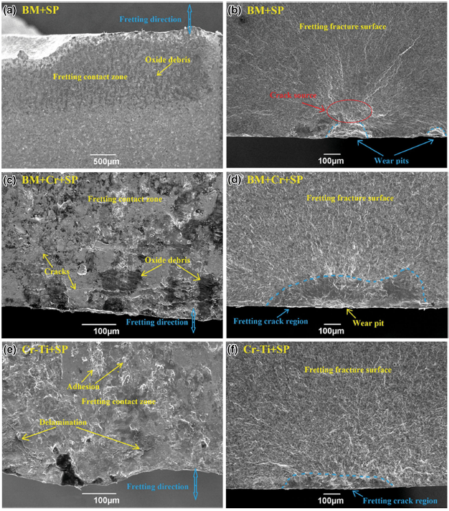
Figure 12 shows the morphologies of the fretting contact zones and FF fracture surfaces of the BM + SP, BM + Cr + SP and Cr-Ti + SP samples. Shot peening could not effectively improve the wear resistance for BM and Cr-Ti samples (Figs. 6, 7); thus, the fretting contact zones of BM + SP and Cr-Ti + SP samples were still seriously worn (Fig. 12a, e). In fact, the residual compressive stress induced by shot peening can inhibit the micro-crack propagation, but with the accumulation of the fretting process, the residual compressive stress may be released and the wear pits may form in the worn area[17, 22]. Some of the micro-cracks initiated from the severe worn areas, or from the bottom of the wear pits, could obtain enough driving force to expand to the inner material [23]. Figure 12a shows that a significant amount of oxide debris filled up the craters in the fretting contact zone. Figure 12b shows that the fatigue crack initiated from the bottom of the large size wear pit. For the Cr-Ti + SP sample, the PF life was 140 times than that of the BM sample, owing to the high residual compressive stress (Fig. 8); however, its FF life was only 3.3 times higher than that of the BM sample (Fig. 10). This may be because the severe wear promoted crack initiation and led to the release of the residual compressive stress. Once the residual compressive stress is released, the crack propagation resistance declines [12]. Figure 12f shows that the fretting crack region had a small depth due to the residual compressive stress decreasing rapidly in the severe worn areas [17, 21]. It is thus clear that the low hardness of the Cr-Ti solid-solution layer caused the significant wear in correspondence with the fretting area and thus should be the main factor limiting the improvement in FF properties for the Cr-Ti + SP sample.
 | Fig. 12 Morphologies of the fretting contact zones a, c, e and the fretting fatigue fracture surfaces b, d, f of the shot peened samples: a, b BM + SP sample; c, d BM + Cr + SP sample; e, f Cr-Ti + SP sample |
Shot peening could improve the toughness of the Cr-alloyed layer to some extent (Fig. 4); thus, the cracks perpendicular to the longitudinal direction were obviously reduced (Fig. 12c). Therefore, the good wear resistance of the Cr-alloyed layer exerted an important influence on the FF properties [5, 6]. It is possible that the FF life of the BM + Cr + SP sample was higher than that of the BM + SP sample and even close to that of the Cr-Ti + SP sample. On the other hand, the low residual compressive stress limited further improvement in the FF properties of the BM + Cr + SP sample. As mentioned above, the poor toughness easily led to cracking or flaking of the Cr-alloyed layer during shot peening process. Thus, the BM + Cr + SP sample had lower residual compressive stress than that of BM + SP sample or Cr-Ti + SP sample. Once the cracks initiated from the worn areas, they were relatively easy to propagate (Fig. 12d). Therefore, the poor toughness is the main factor that limited the further improvement in FF properties for the BM + Cr + SP sample.
(1) The fretting fatigue properties of the modified Ti6Al4V alloy depended on the trade-off between two factors: the wear resistance and the fatigue resistance. High surface hardness and excellent toughness are beneficial to the wear resistance and the fatigue resistance, respectively.
(2) The hard Cr-alloyed layer could effectively resist the wear in the fretting area, but its poor toughness caused the fatigue resistance to drop sharply and thus led to a premature failure during the fretting fatigue test. Moreover, the poor toughness also had a negative effect on the shot peening process. Finally, a relatively low residual compressive stress was induced in the Cr-alloyed layer surface. Therefore, the Cr-alloyed layer combined with shot peening only slightly increased the fretting fatigue properties. It may be concluded that the poor toughness is the main factor limiting the improvement in the fretting fatigue properties through this combined treatment.
(3) The severe wear in the fretting area and the high temperature in plasma chromizing process were the main factors that limited the improvement in the fretting fatigue properties of the Ti6Al4V alloy by introduction of the Cr-Ti solid-solution layer. However, due to its excellent toughness, the Cr-Ti solid-solution layer had relatively better fretting fatigue properties than the Cr-alloyed layer. Shot peening only slightly increased the surface hardness of the Cr-alloyed layer. So the Cr-Ti solid-solution layer was still worn seriously during the fretting process after shot peening. The severe wear promoted crack initiation and led the release of the residual compressive stress in the fretting areas. The Cr-Ti solid-solution layer combined with shot peening only slightly increased the fretting fatigue properties. The low hardness that led to severe wear in the fretting area is the main negative factor for this combined treatment.
(4) Based on the comparison of the Cr-alloyed layer and the Cr-Ti solid-solution layer, it is clear that both the wear resistance and the fatigue resistance exert important influence on the fretting fatigue properties. A modified layer with a good balance between hardness and toughness may have greater potential to improve the fretting fatigue properties when combined with shot peening post-treatment.
The authors have declared that no competing interests exist.
| [1] |
|
| [2] |
|
| [3] |
|
| [4] |
|
| [5] |
|
| [6] |
|
| [7] |
|
| [8] |
|
| [9] |
|
| [10] |
|
| [11] |
|
| [12] |
|
| [13] |
|
| [14] |
|
| [15] |
|
| [16] |
|
| [17] |
|
| [18] |
|
| [19] |
|
| [20] |
|
| [21] |
|
| [22] |
|
| [23] |
|