

1 Introduction
Sliding gate system can be used during many steel teeming processes of different metallurgical containers, such as ladle, tundish and converter [1,2,3]. With the ongoing improvement of automatic production level and the steel cleanliness requirements of high value-added products, many technical bottlenecks about the sliding gate system need to be solved urgently [4]. First, during the continuous casting process, nozzle sand, a filling material of the upper nozzle, enters the tundish along with liquid steel directly, causing serious pollution to the liquid steel [5, 6]. Beyond that, the automatic casting ratio of continuous casting ladle cannot reach 100%. If the ladle cannot pour automatically, an artificial method of burning oxygen is needed to assist steel teeming process, which will increase labor and pollute liquid steel seriously [7, 8]. Second, during the ingot casting process, the automatic casting ratio can reach only about 80%, which greatly influences the production rhythm and increases the labor cost. In addition, in order to improve the quality of ingot products, it is necessary to beforehand outflow 500 kg liquid steel before the casting process to avoid the nozzle sand entering ingot mold, which reduces the yielding rate of liquid steel. And, the nozzle sand is not only expensive, but also pollutes the production environment [9].
Because the electromagnetic induction-controlled automated steel teeming (EICAST) system is expected to solve the above problems of the sliding gate system, a lot of studies have been done [10,11,12,13]. This technology has successfully applied the induction heating to the steel teeming process of ladle, and it is a new technology to control the steel teeming process [14]. After filling in the upper nozzle, Fe-C alloy particles (instead of nozzle sand) will be divided into three layers under the action of high-temperature liquid steel, including melting layer, blocking layer and original layer. Among them, the blocking layer needs to be melted by Joule heat generated by an induction coil in a refractory brick. So, the height and location of the blocking layer are the key variables of the EICAST technology [15]. Moreover, the height of the blocking layer directly affects the structure size of the induction coil, and the location of the blocking layer also has an effect on the installation location of the coil [16]. Because the blocking layer is formed by heat transfer from liquid steel, the liquid steel temperature during the refining process, the holding time of liquid steel in ladle before steel teeming process and the composition of the Fe-C alloy particles filled in the upper nozzle are main factors affecting the blocking layer. Among them, the liquid steel temperature mainly determines the initial temperature of heat transfer heat source. The holding time of liquid steel in ladle is the heat transfer time of the blocking layer formation. The alloy composition of filling particles determines the relevant parameters of heat transfer medium. However, in the practical production process, the refining temperature and the holding time of each steel grade cannot be changed or adjusted arbitrarily. Therefore, with an aim to ensure being most effectively heated by the induction coil, the height and location of the blocking layer can be modified by changing the composition chemistry of alloy particles filled in the upper nozzle. It is of great significance to analyze the influence of the above factors on the height and location of the blocking layer.
By setting different parameters in a series of small laboratory experiments, Shi et al. [17] predicted the effect of the liquid steel temperature and the holding time on the height of the blocking layer. However, the holding time in their experiments was much less than that in the actual ladle in a steelworks, and the crucible used in the experiments was very small; therefore, they could not simulate the practical working condition. He et al. [18] revised the criterion temperature of the blocking layer in numerical simulation by comparing the blocking layer location measured by large experiments with the simulation results. And in their research, the influencing factors of the blocking layer were briefly described, but the change law of the blocking layer had not been specifically analyzed. Therefore, on the basis of previous studies, the influence of three factors on the height and location of the blocking layer was analyzed by numerical calculation in this paper, and the variation law of the blocking layer was summarized. The simulation results were verified by 40 t ladle industrial experiments. After that, the analysis procedure of coil size and its installation location in the EICAST system were determined.
2 Research Methods
2.1 Numerical Simulation
With the reference of the refractory brick in the actual production in a steelworks, the numerical calculation model of the EICAST system is established, as shown in Fig. 1. The three-dimensional model is shown in Fig. 1a, and the main sizes are shown in Fig. 1b. The length, width and height of the refractory brick are 550 mm, 350 mm and 350 mm, respectively. The induction coil is mounted in the refractory brick, and the top side of copper coil is 150 mm away from the top surface of the refractory brick.
Fig. 1

Fig. 1
Numerical model: a model, b main sizes (unit: mm)
To simplify the calculation, the following assumptions are made:
1. During calculation process, the gap between the refractory brick and the upper nozzle is ignored, and the material of the upper nozzle and the refractory brick is the same.
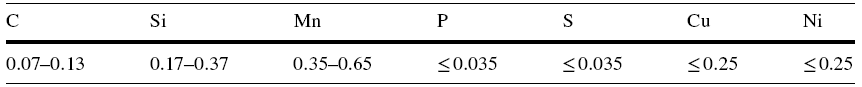
2. Alloy composition of filling particles in the upper nozzle is the same as that of liquid steel, as shown in Table 1.
3. Induction coil is not cooled during holding liquid steel process, so it is considered that the coil is filled with static air. Four sides of the refractory brick are adiabatic. Natural convection occurs between the bottom surface of the refractory brick and the air.
4. The density, specific heat capacity and thermal conductivity of the refractory brick do not change with temperature.
Temperature distribution in the Fe-C alloy particles and the refractory brick can be described by the following heat conduction differential equation:
$\rho c\frac{\partial T}{\partial \tau } = \frac{\partial }{\partial x} \left( {\lambda \frac{\partial T}{\partial x}} \right) + \frac{\partial }{\partial y} \left( {\lambda \frac{\partial T}{\partial y}} \right) + \frac{\partial }{\partial z} \left( {\lambda \frac{\partial T}{\partial z}} \right) + q_{v},$
where ρ is the material density, kg/m3; c is the specific heat capacity, kJ/(kg °C); T is the temperature, °C; τ is the time, s; λ is the thermal conductivity, W/(m °C); qv is the internal heat source intensity, W/m3. Because the induction heating process is not considered in this study, \(q_{v} = 0\).
In the calculation process, the density, specific heat capacity and thermal conductivity of the refractory brick are 3040 kg m-3, 1.13 kJ kg-1 °C-1 and 2.9 W m-1 °C-1, respectively [19]. The thermal conductivity and the specific heat capacity of the copper coil change with temperature [20]. In addition, different Fe-C alloy particles or alloy steel particles may be used as filling materials when different steel grades are produced. Alloy composition has a significant effect on the alloy melting point. Therefore, according to references [20, 21], the thermal conductivity and specific heat capacity of different composition Fe-C alloys and alloy steels at different temperatures are set, respectively.
According to the actual thermal cycle of ladle in a steelwork, the temperature variations of the top surface of the refractory brick and Fe-C alloy particles are set as shown in Fig. 2. To analyze the influence of different factors on the height and location of the blocking layer, the liquid steel temperature is valued between 1500 and 1700 °C, and the holding time is valued between 30 and 180 min. The heat transfer coefficient of static air is 5 W/(m2 °C), and the heat transfer coefficient of natural convection is 15 W/(m2 °C).
Fig. 2
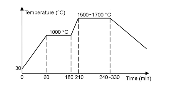
Fig. 2
Temperature condition of the top surface of the Fe-C alloy particles and the refractory brick
2.2 Experimental
Six K-type thermocouples were installed in the refractory brick of a 40 t ladle in a steel plant, and the purpose was to measure the temperature distribution of the refractory brick during the refining process after ladle was filled with liquid steel. Installation locations of thermocouples in the refractory brick are shown in Fig. 3. The steel grade used in the experiment was Cr12MoV, the liquid steel temperature was 1550 °C, and the holding time of liquid steel in ladle was 180 min. Because of meeting the experiment requirements, alloy composition of filling particles in the upper nozzle is also listed in Table 1.
Fig. 3
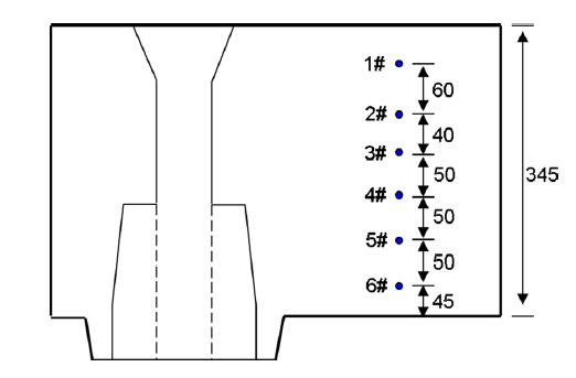
Fig. 3
Installation locations of thermocouples in the refractory brick (unit: mm)
3 Results and Discussion
Temperature gradient is the basic cause of the formation of the blocking layer in the upper nozzle. When numerical simulation method is used to analyze the height and location of the blocking layer, the sintering temperature and melting point of Fe-C alloy cannot be directly used to judge the height and location of the blocking layer because of the transition layer and the expansion layer, and the criterion temperatures of the top and bottom surfaces of the blocking layer are modified to 919 °C and 428 °C, respectively [18]. Therefore, the determination processes of the height and location of the blocking layer in this paper are as follows: the temperature fields of the refractory brick and filling alloy material are calculated firstly; then, the positions of the top and bottom surfaces of the blocking layer are determined according to the temperature field and the criterion temperatures; finally, the height and location of the blocking layer are calculated by the positions of the top and bottom surfaces.
3.1 Correctness Verification of Numerical Simulation
In order to validate the accuracy of numerical model, when the liquid steel temperature is 1550 °C and the holding time is 180 min, the temperature distribution of the refractory brick is calculated by using the established calculation model. At the same time, in the industrial experiments of the 40 t ladle, K-type thermocouples are used to measure the temperatures in the refractory brick during the refining process. 3# thermocouple is damaged in the experiment process. Because of high temperature, 1# thermocouple is damaged after the first experiment, so only one value is obtained. As shown in Fig. 4, it can be seen that the measured temperature decreases with the increase in the distance between measuring point and the top surface of the refractory brick. Moreover, the numerical simulation results are in good agreement with the experimental results.
Fig. 4
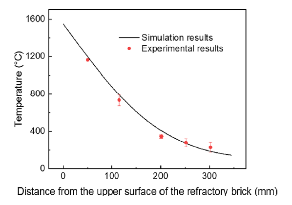
Fig. 4
Comparison and analysis of numerical results and experimental results
3.2 Effect of the Liquid Steel Temperature and the Holding Time on Height and Location of the Blocking Layer
3.2.1 Effect of the Liquid Steel Temperature
For different kinds of steel, because of their different production requirements, the refining temperatures of liquid steel are different. The liquid steel temperature is a very important operation parameter or control parameter during the refining process. At the same time, it also has an important impact on the height and location of the blocking layer. For different steel grades, the liquid steel temperatures are valued between 1500 and 1700 °C. When the holding time is 120 min, and the alloy composition of filling particles is the same as that in Table 1; temperature distributions of the refractory brick and filling alloy material in the upper nozzle at different liquid steel temperatures are calculated. As shown in Fig. 5a, b, the heights and locations of the blocking layer are determined according to the temperature distributions and the criterion temperatures, respectively.
Fig. 5
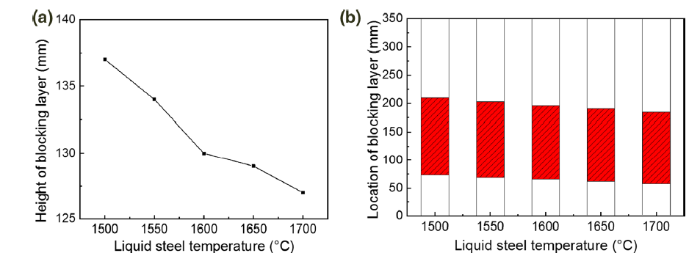
Fig. 5
Heights and locations of blocking layer at different liquid steel temperatures: a heights, b locations
From Fig. 5a, it is obvious that the height of the blocking layer decreases with the increase in the liquid steel temperature when the ladle is filled with liquid steel for a certain time. In Fig. 5b, the total filling height of Fe-C alloy particles indicated by ordinate is 350 mm. The location of the blocking layer changes obviously at different liquid steel temperatures. With the increase in the liquid steel temperature, the decreasing rate of the top surface location of the blocking layer is slightly higher than that of the bottom surface location of the blocking layer. The main reason for this phenomenon is the temperature gradient of filling alloy particles in the upper nozzle from top to bottom. Because of the higher temperature of the top surface of the blocking layer, the increase in the liquid steel temperature has more obvious effect on the heat transfer process of the top surface, but less effect on the heat transfer process of the bottom surface. Moreover, the location of the blocking layer moves downward with the increase in the liquid steel temperature.
3.2.2 Effect of the Holding Time
After the ladle is filled with liquid steel, the temperature of the alloy particles will be gradient distribution from top to bottom along with the heat transfer process. The temperature of the filling particles in the upper nozzle increases as prolonged holding of the ladle filled with liquid steel. When the liquid steel temperature is 1600 °C and the chemistry composition of filling particles is the same as that in Table 1, the height of the blocking layer and its top and bottom surface locations are calculated, as shown in Fig. 6.
Fig. 6

Fig. 6
Heights and locations of the blocking layer at different holding times: a heights, b locations
It is shown in Fig. 6a that the height of the blocking layer will become higher with the increase in the holding time, thus it will also lead to the increase in coil length. In addition, with the increase in the holding time, the growth rate of the height of the blocking layer increases continuously. When the holding time is 180 min, the height of the blocking layer even reaches 159 mm. It has exceeded the 150 mm design height of the induction coil, which is extremely disadvantageous to the coil’s installation and its electrification work.
As shown in Fig. 6b, when the holding time is shorter, the location of the blocking layer is higher, and the corresponding installation location of the induction coil is higher, which will lead to higher environment temperature of the induction coil. It is not conducive to ensure coil safety and its service life. With the increase in the holding time of liquid steel in ladle, the locations of the top and bottom surfaces of the blocking layer will move downward gradually. At this time, the installation location of the coil will also move downward, which is favorable to reduce the environment temperature of the induction coil in the refractory brick. At the same time, with the prolongation of the holding time, the decrease amplitude of the top surface location decreases gradually, while the decrease amplitude of the bottom surface location increases gradually. The reason is that the heat transfer process tends to heat saturation state gradually; the temperature change of the top side is no longer drastic, but the temperature increase amplitude of the bottom side is increasing. Therefore, when the holding time is too long or too short, the height and location of the blocking layer need to be regulated by other means.
3.2.3 Comprehensive Analysis
Both the liquid steel temperature and the holding time can affect the height and location of the blocking layer. To analyze and compare the effect of two factors comprehensively, when the alloy composition of filling particles is the same as that in Table 1, the height and location of the blocking layer (thin cylinder) and the height of the original layer (crude cylinder) at different liquid steel temperatures and different holding time are shown in Fig. 7. Similarly, the total filling height of alloy particles is 350 mm (as shown in the coordinate system). Obviously, the height of the blocking layer decreases with the increase in the liquid steel temperature, but increases with the increase in the holding time of liquid steel in ladle.
Fig. 7

Fig. 7
Heights and locations of the blocking layer at different liquid steel temperatures and different holding time
Generally, the height of the blocking layer decreases with the increase in the liquid steel temperature. However, when the liquid steel temperature is 1700 °C and the holding time is 180 min, the height of the blocking layer is the largest (166 mm), and the location of the blocking layer is the lowest. At this time, the height of the original layer is 0 mm. Therefore, it can be concluded that the influence of the holding time on the blocking layer height is greater than that of the liquid steel temperature. When the liquid steel temperature is 1700 °C and the holding time is 30 min, the height of the blocking layer is the smallest (118 mm). When the liquid steel temperature is higher and the holding time is shorter, the height of the blocking layer is smaller. When the liquid steel temperature is 1500 °C and the holding time is 30 min, the height of the blocking layer is the highest, that is, the height of the melting layer is the smallest. At this time, the height of the blocking layer is 129 mm and the height of the melting layer is 105 mm. In conclusion, with the change of the liquid steel temperature and the holding time, the condition of the maximum blocking layer height is consistent with that of the lowest blocking layer location, but the condition of the minimum blocking layer height is not consistent with that of the highest blocking layer location. The above differences are due to the greater influence of the holding time on the height and location of the blocking layer.
3.3 Effect of the Alloy Composition on the Height and Location of the Blocking Layer
Once the steel grade is determined, the production process cannot be changed greatly. Therefore, in many cases, the height and location of the blocking layer are extremely disadvantageous to the coil design and installation. In order to apply the EICAST system to the production processes of all steel grades, it is necessary to adjust the height and location of the blocking layer by other methods. Chemical composition of alloy particles has a great influence on its microstructure and physical properties [22, 23]. With the change of alloy composition, the thermophysical properties of filling alloy particles will also change significantly. Therefore, the height and location of the blocking layer can be changed by changing the alloy composition of filling alloy particles in the upper nozzle.
In order to facilitate analysis, several alloy particles with different compositions are selected as filling materials in the upper nozzle. When the liquid steel temperature is 1600 °C and the holding time is 120 min, the heights and locations of the blocking layer are calculated, as shown in Fig. 8. It can be seen that the heights and locations of the blocking layer are different for different steel grades when alloy particles with the same composition as liquid steel are used. The element content in the filling alloy particles also has an important influence on the height and location of the blocking layer [24]. For carbon steel, with the increase in C content, the height of the blocking layer decreases gradually, and the location of the blocking layer moves upward gradually. During this process, the height of the blocking layer decreases greatly, but the location of the blocking layer moves upward slightly. Therefore, in order to ensure the height and location of the blocking layer are in a certain range and direct the coil’s installation in the EICAST system, the influence of the liquid steel temperature and the holding time on the blocking layer can be adjusted by changing the alloy element content generally.
Fig. 8

Fig. 8
Heights and locations of the blocking layer at different alloy compositions
4 Determination of Coil Length and Location
After the above analysis, taking a 40 t ladle for ingot casting as an example, the average liquid steel temperature is 1550 °C, and the holding time of liquid steel in ladle is 180 min. When the alloy composition of filling particles is the same as that in Table 1, the height and location of the blocking layer are calculated, as shown in Fig. 9. At this time, the height of the blocking layer is 129 mm, the height of the melting layer is 120 mm, and the height of the original layer is 101 mm. The height and location of the blocking layer are within a suitable range, so the size design and installation location of the induction coil can be carried out directly.
Fig. 9

Fig. 9
Height and location of the blocking layer in a 40 t ladle with the EICAST system
In summary, during the application process of the EICAST technology, the liquid steel temperature, the holding time of liquid steel in ladle and the alloy composition of filling particles in the upper nozzle all affect the height and location of the blocking layer. The height and location of the blocking layer directly affect the coil size and its installation location in the refractory brick. Therefore, before determining the coil size and its installation location, it is necessary to determine the height and location of the blocking layer according to the steel grade and its production process. If the height and location of the blocking layer after considering the liquid steel temperature and the holding time are not conducive to the coil design and installation, the height and location of the blocking layer must be adjusted by changing the alloy composition or element content of filling particles until they are within an appropriate range. Therefore, the determination process of coil size and its installation location is shown in Fig. 10.
Fig. 10

Fig. 10
Determination process of coil length and its installation location
5 Conclusions
On the basis of experimental verification, the effect of different factors on the height and location of the blocking layer in the EICAST system is analyzed by numerical simulation, and their changing rules are obtained. After that, the determination process of coil size and its installation location in the EICAST system are analyzed. Main conclusions are as follows:
1. The location of the blocking layer moves downward with the increase in the liquid steel temperature and the holding time of liquid steel in ladle. The height of the blocking layer decreases with the increase in the liquid steel temperature, but it increases with the increase in the holding time. Comparatively speaking, the influence of the holding time in ladle on the height and location of the blocking layer is greater than that of the liquid steel temperature.
2. The alloy composition of filling particles has a significant impact on the height and location of the blocking layer. For carbon steel used widely, with the increase in C content in the alloy particles, the height of the blocking layer decreases gradually, and the location of the blocking layer moves upward gradually.
3. Before determining the coil size and its installation location, it is necessary to analyze the influence of the liquid steel temperature and the holding time on the height and location of the blocking layer. If the height and location of the blocking layer are not conducive to the coil design and its installation, it can be adjusted by changing the alloy composition or element content until they are within the appropriate range.
Acknowledgements
This research was financially supported by the National Natural Science Foundation of China (Grant No. U1560207) and the Liaoning Innovative Research Team in University (Grant No. LT2017011).
Reference
- About AMSE
- Authors and reviewers
- Contact
E-mail: ams@imr.ac.cn
Address: 72 Wenhua Road, Shenyang, Liaoning, 110016, China
 WeChat
- Copyright © Editorial Office of Acta Metallurgica Sinica (English Letters), All Rights Reserved.
