Search for articles:
Xing-Chen Liu , Zhi-Ming Zhang
Corresponding authors:
Received: 2019-03-12
Revised: 2019-04-8
Online: 2019-12-10
Copyright: 2019 Editorial board of Acta Metallurgica Sinica(English Letters) Copyright reserved, Editorial board of Acta Metallurgica Sinica(English Letters)
More
Abstract
In pressurized water reactor, fretting corrosion has become the main reason for the failure of 690TT heat exchanger tubes. The effect of temperature on the fretting corrosion behavior between 690TT tube and 405 stainless steel (SS) bar has been studied during 106 fretting cycles. The overall average coefficient of friction (COF) values descends with an increase in test temperature, while the width of worn scar becomes wider. The severest fretting corrosion happens when the test temperature is at 100 °C. The wear mechanism differs at different test temperatures, from adhesive wear at room temperature to abrasive wear and delamination at 100 °C, to abrasive wear at 200 °C. Deformation slips, high residual strain concentration, and micro-cracks are found which are disadvantageous for the further service performance of the tubes.
Keywords:
In the pressurized water reactor (PWR) nuclear power plants (NPPs), nickel-based alloy 690TT is one of the most widely used materials for steam generator (SG) heat exchanger tubes, because of its excellent characteristic on the resistance of corrosion and stress corrosion cracking (SCC) [1]. Since 2010, the failure of the SG tubes caused by SCC has significantly decreased as more and more 690TT rather than 600 and 800 tubes are used [2]. Up till now, no SCC failure of 690TT tube has been reported. However, structure wear has already become the main reason for the failure of SG tubes, especially fretting corrosion between SG tubes and the anti-vibration structures [3].
Fretting corrosion refers to tiny relative oscillation, usually with a displacement in micrometer order, between two contacted or semi-contacted bodies or structures in corrosive environments. In NPPs, flow-induced vibration exists around the SG tubes, and as such, minor relative displacements are generated between the tubes and their supports in secondary water, and eventually, fretting corrosion occurs [4]. Therefore, for SG tubes, fretting corrosion is ineluctable and it can result in tube thinning or even leak of radioactive substances [5]. Plenty of researchers have focused on the fretting wear behavior of Alloy 690TT alloy between various materials [6, 7, 8, 9, 10]. It is doubtless that mechanical parameters, including displacement amplitude [11, 12], normal force [13, 14] and frequency [15, 16] are crucial factors affecting the fretting wear process.
However, except for the three mechanical parameters mentioned above, the environment condition also affects the fretting corrosion process vitally [10, 17]. On one hand, the environment has a significant effect on the corrosion behavior of both mated materials. For secondary water in PWRs, the effects on corrosion behavior of stainless steels and nickel-based alloys have been widely studied, including the temperature, pressure, pernicious ions and their contents, dissolved oxygen (DO) content and other water treatment [18, 19, 20, 21]. For instance, Kuang et al. studied oxide film formed on 304 SS surface in high-temperature water with different DO concentration and found that relative Cr content in the oxide film increased with the decrease in DO, as well as more spinel oxides and less hematite formed on the fresh sample [22]. On the other hand, the corrosion behavior of the mated materials could be the main factor in the fretting wear behavior of both mated materials as well. Yun et al. investigated the fretting wear behavior between 690 SG tube and 409 SS affected by different thickness of oxide film and found the wear resistance of 690 increased with increasing thickness of oxidation film [23].
For secondary water condition in PWR, the temperature is a crucially important parameter as it affects the fretting corrosion behavior significantly. Some previous researchers have focused on the influence of temperature and made great contributions to reveal the underlying reasons. However, up to now, most of the researches were carried out in the water lower than 100 °C, at low frequency or with fairly large displacement, which may alter the result from the ones in actual operating conditions in NPPs [6, 9]. Some researches performed in high-temperature high-pressure (HTHP) water are reported [14, 24, 25]; however, the test term during the fretting corrosion tests is a little short. The research on long-term (≥ 106 fretting cycles) fretting corrosion characteristics of Alloy 690TT alloy in HTHP water is still devoid. In addition, the evaluation of long-term fretting corrosion behavior, which occurs for the actual SG heat exchanger tubes, may be inexact by using the data from short-term tests. As a result, it is vital to research on the influence of temperature on the long-term fretting corrosion which will be discussed in this paper.
In this paper, the fretting corrosion behavior between 690TT tubes and 405 SS anti-vibration bars are studied at different temperature with the aim of clarifying the influence of temperature on the fretting corrosion behavior between them with well-controlled mechanical parameters in simulated secondary water.
The as-received Alloy 690TT tubes and 405 SS samples from anti-vibration bars applied in domestic NPP were prepared. The chemical compositions for both materials are listed in Table 1. The sizes of 690TT tubes used in the tests were 20.00 mm in length, 19.05 mm in outer diameter and 1.09 mm in thickness, while 405 SS cylinders with the diameter of 4 mm were used as the mated wear couples. 690TT tube has a surface roughness (Ra) of 0.180 μm while 405 SS bar has one of 0.469 μm. During the sample preparation process, the surfaces of the samples were well protected, so that both the tube surface and the head surface of the cylinder were used in the initial state. The samples were all cleaned ultrasonically for 30 min in ethanol and then dried in hot compressed air before being installed on the testing equipment. The microstructures of mated materials were observed by optical microscopy (OM) and the values of surface roughness (Ra) were measured by Links 2205 surface roughness tester. The hardness was achieved by MHVD-1000AP micro-hardness tester. The load was 0.98 N while the holding time was 15 s.
Table 1 Chemical compositions for 690TT and 405 SS (wt%)
| Fe | Ni | Cr | Si | Mn | Al | Ti | C | S | P | |
|---|---|---|---|---|---|---|---|---|---|---|
| 690TT | 9.81 | Bal. | 29.55 | 0.06 | 0.01 | 0.11 | 0.12 | 0.022 | < 0.01 | < 0.01 |
| 405SS | Bal. | 0.55 | 13.51 | 0.76 | 0.85 | 0.13 | - | 0.060 | 0.018 | 0.025 |
As shown in Fig. 1, all the tests were accomplished by using a HTHP fretting wear equipment. The equipment has been introduced in detail in Ref. [26]. In brief, the equipment consists of an autoclave, a vibration actuator, a normal load control system, water chemistry measuring and adjusting system, a heating system, and a water circulation system.
Fig. 1 Schematic diagram of the high-temperature high-pressure fretting wear testing equipment
The displacement sensor (eddy current sensor) is located outside the autoclave on the opposite side of the vibrator to avoid its effect. The detection range is from 0 to 2 mm with an accuracy of 0.4 μm. The measured displacement will be sent back to the controller and if it is deviated from the set value, the controller will adjust the output power of the vibrator to calibrate the displacement to make it stable during the whole experiment.
The normal load is applied by a stepping motor. The 405 SS sample is fixed in the autoclave and the load is applied at the bottom of the fixture using to fix 690 TT sample to exclude the influence of gravity. The load rod is sealed with rubber O-ring and the force sensor is located closer to the autoclave than the sealing system to avoid the effect of the friction between rod and O-ring. The value of the normal load is controlled precisely by the numerical control system using the feedback data from the force sensor automatically. Additionally, pressure balancing mechanism is used to make the pressure equal above and under the force sensor so as to exclude the effect of the water pressure in the autoclave.
The oscillating arm is inserted into the autoclave and sealed with rubber O-rings on both sides. The oscillating arm and the fixture are locked as an entire rod and two sets of force sensors are located on both sides of the oscillating arm. The force sensors are located at the extended segment of the autoclave with cooling system and are closer to the autoclave than the rubber O-rings. During the fretting process, the data of force will be collected by both sets of force sensors synchronously and the actual friction force between the friction pairs can be calculated automatically to exclude the friction force of the sealing system.
In Table 2, the parameters used in the fretting tests were listed in detail. The temperature span of the tests was from room temperature (RT) to 200 °C, while the pressure was set at 12.5 MPa to avoid the evaporation of the pure water and stabilize the water environment, which also was normalized. The DO content of the water was controlled to be below 5 μg/L during the whole test by bubbling pure nitrogen into the autoclave throughout the experiment. The frequency (40 Hz), normal force (40 N) and fretting amplitude (± 100 μm) were set to be close to the real values that SG tube fretting corrosion happens in NPPs. The contact configuration between 690TT tube and 405 SS cylinder was schematically shown in Fig. 2. The width of the contacted area b and initial contact stress P0 of 690 TT tube mated with 405 SS were calculated and listed in Table 3. The fretting cycles were 106 to simulate the practical long-term fretting wear evolutionary trend more accurately. The data acquisition interval was 0.1 ms, meaning that 250 points were collected in a fretting cycle at 40 Hz to ensure the accuracy of fretting coefficient. The immersion time of all test samples under set temperature was 18 h before the fretting corrosion tests started.
Table 2 Parameters for the fretting corrosion tests of 690 TT mated with 405 SS
| Testing parameters | Value (unit) |
|---|---|
| Temperature | RT, 100 °C, 200 °C |
| Pressure | 12.5 MPa |
| DO content | < 5 μg/L (by weight) |
| Solution | Pure water |
| Frequency | 40 Hz |
| Displacement amplitude | ± 100 μm |
| Normal force | 40 N |
| Total cycles | 106 |
| Immersion time before fretting | 18 h |
Fig. 2 Schematic diagram of the contact configuration between 690TT tube and 405SS cylinder
Table 3 Width of contacted area and initial contact stress of 690 TT tube mated with 405 SS
| Temperature (°C) | b (μm) | P0 (MPa) |
|---|---|---|
| RT | 87.48 | 72.77 |
| 100 | 87.81 | 72.50 |
| 200 | 88.27 | 72.13 |
After fretting corrosion tests, a MicroXAM-3D (America ADE) three-dimensional surface morphology analyzer was applied to study wear depths and topographies of the worn scars. Furthermore, detailed morphology and main chemical composition (Cr, Ni, Fe, and O) distribution across the worn scars were studied by a field emission scanning electron microscope equipped with an energy dispersive X-ray microanalysis (SEM/EDS, FEI XL30). Cross-sectional samples were prepared by a diamond saw. The cross-sectional microstructures of the worn scars and the elements distributions were also studied by SEM/EDS. Cross-sectional microstructure of the sample tested at RT was studied by electron backscattering diffraction (EBSD) with a scanning voltage of 25 kV and a scanning step size of 0.3 μm. Orientation imaging microscopy (OIM) software was used to analyze the EBSD data.
Figure 3a, b presents the OM microstructures of 690TT and 405 SS, respectively. The 405 SS is composed by light ferrite and darker band structure, all of which are parallel to the length direction of the anti-vibration bar. However, alloy 690TT only has a single austenite microstructure. During the thermal treatment process, Cr23C6 were formed along the grain boundaries. The grain size with an average value of ~ 60 μm is not uniform. The hardness of both materials was measured and shown in Fig. 3c. It can be observed that the hardness of 405 SS is just a little higher than that of 690TT tube (~ 2 HV).
Fig. 3 Microstructure of 405 SS a and 690TT b observed by optical microscope and the micro-hardness c
Figure 4 shows the variation of COF, which equals to the tangential force divided by the normal force, with the increment of fretting cycle number (N) under different temperatures during the fretting corrosion process. It can be observed that the overall average of COF value descends when the temperature increases. And there is obviously a peak point at low cycles (about N = 200) when the samples were tested under 100 °C and 200 °C, which is not found when tested at RT. When the fretting cycles are larger than 103, the tendency of the curves becomes similar, thus it is reasonable to summarize the evolution of COF curves into six stages as a function of cycle numbers. (1) Initial stage (N < 50): at the very first cycles, the COF values are relatively small and increase moderately. It is because that there are some adsorption products or oxide films on the surface of the fretting pairs, as well as some discontinuous salient areas due to the untreated bare surface. The erasure process of the imperfect flat surface resulted in the initial stage with the low and slowly increasing values of COFs. This stage is also called the run-in stage [9]. (2) Sharply increasing stage (50 < N < 200): as the removal of the adsorption products or oxide films after certain cycles, direct contact of the fretting pairs happens (metal-to-metal contact) and result in the stick phenomenon, hence the COFs increase sharply. This stage represents the two-body contact between the friction pairs. (3) Decreasing stage (200 < N < 1000): the peak points and the rapid fall of the COF curves only appear at 100 °C and 200 °C which mean that the contact form has been transferred to three-body contact as the oxidized wear debris plays a significant role of lubrication. Meanwhile, it is inferred by no peak point existing at RT condition that there is no obvious three-body contact and oxidized wear debris in the RT water at this stage. (4) Relatively steady stage (1000 < N < 50,000): after wildly fluctuating at low cycles, the speed of the wear at the tube surface and the elimination of the fretting corrosion products including oxidized wear debris and delamination substance become close. The relative equilibrium is maintained at this stage. (5) Re-ascending stage (50,000 < N < 200,000): after being steady for around 200,000 cycles, the COF of all curves re-ascend to a relatively high value. This change is rarely reported in the previous papers due to the limitation of the fretting cycles which are always < 100,000 in most published researches [10, 11]. This phenomenon generates due to various reasons, including broadening of the contact area, the accumulation of fretting corrosion products and the delamination after high fretting cycles. (6) Re-stable stage (200,000 < N < 1,000,000): when the fretting cycles surpass a relatively high number (N = 200,000 or more), the values of COF become stable again until the end of the tests with the total fretting cycles N = 1,000,000. This means that the dynamic equilibrium is established again which is not only the balance between production and elimination of the fretting corrosion products but also the approximate rate between delamination at the surface and inward extension of tribologically transformed structure layer at the subsurface.
Fig. 4 Friction coefficients as a function of fretting cycle numbers at different temperature in pure water
The entire SEM morphologies of worn scars formed on the 690TT tubes after being tested at different temperatures and their corresponding 3D profile micrographs are shown in Fig. 5. It could be found that the width of the worn scar broaden when the temperature increases and corrosion products and exhausted debris occur and accumulate at the crevice area formed between the 690TT tubes and the 405 SS bars. It is obvious that the crevice area at 100 °C has the largest amount of accumulated debris and oxides while the one at RT has the least amount. In addition, some pits occur separately at partial regions of the crevice area of the RT sample, as pointed out by the yellow arrow in Fig. 5a. From the 3D-profile micrographs, it can be found that the worn scar is shallow overall and some deep holes are observed in the worn scar. On the contrary, the worn scars of samples tested at 100 °C (Fig. 5b) and 200 °C (Fig. 5c) exhibit different morphologies. Furrows with the same direction of vibration direction exist at the whole worn scars with a relatively random distribution. Compared with the furrows at 200 °C, the furrows at 100 °C is longer and deeper.
Fig. 5 Surface morphologies of the worn scars on 690TT tubes against 405 SS cylinder at different temperature in pure water, a-c by SEM, d-f 3D morphologies by 3-D surface morphology analyzer
The morphologies of all worn scars tested at different temperatures are shown in detail in Fig. 6. From Fig. 6a-c, it can be noticed that a large amount of torn holes and attachments (transferred 405 SS) rather than furrows exist at the worn scar which implies the contact of friction pairs is under stick mode and adhesive wear dominates the fretting procedure at RT. From Fig. 6c, it can be easily observed that at the edge of abrasive wear and adhesive wear regions, the depth of furrows is far shallower than the torn holes, which means the main abrasion is caused by adhesive wear at RT.
Fig. 6 Surface morphologies of the worn scars on 690TT tube at higher magnifications by SEM, a-c for sample tested at RT, d-f for sample tested at 100 °C, g-i for sample tested at 200 °C
Figure 6d-f reveals a completely different worn scar morphology at 100 °C compared with that observed at RT. The furrows distribute throughout the worn scar and possess the deepest depth among the three scars. In addition, delamination occurs in several areas but is relatively shallower. The delaminated plates were oxidized during the fretting wear process. As a result, abrasive wear is the main abrasion form, meanwhile, delamination also happens.
Figure 6f-i shows the worn scar morphology formed at 200 °C which is somehow similar to that at 100 °C. Differently, the depth of the worn scar is obviously shallower than at 100 °C. As shown in Fig. 6i, the furrows lie on a glaze layer which is flat and smooth with some micro-cracks on it. It is obvious to find that the abrasive wear dominates the fretting corrosion process at 200 °C.
EDS line scanning is used to study the chemical composition distributions across the worn scars on 690TT tube after the fretting corrosion tests at different temperatures which are shown in Fig. 7. It is revealed from Fig. 7a and d that severe material transferring occurs between the 690TT tube and the 405 SS bar, as higher Fe content is found at some areas across the worn scar on 690TT tube whose main chemical composition is Ni. However, the transferred 405 SS is somewhat oxidized during the fretting corrosion process as higher O content is also observed at the zones where Fe content is high. In addition, the chemical composition in the torn hole is similar to that of 690TT matrix, which means the bottom of the hole is bare 690TT though it is also somewhat oxidized. As for worn scars formed during the fretting corrosion process at 100 °C (Fig. 7b, e) and 200 °C (Fig. 7c, f), higher O content is observed both at the worn scar zones and the crevice areas than that at RT. At 100 °C, no obvious material transferring is observed at the worn scar area. In addition, due to the severe abrasive wear, large amount of debris, including 405 SS, are ejected out of the contacted area and this is the reason why Fe-rich zone is found at the crevice area. However, at 200 °C, the chemical composition across the worn scar is very complex, composing Fe-rich debris and bare 690TT area. Fe-rich oxides are also observed at the crevice area.
Fig. 7 EDS line scanning across the worn scars on 690TT tube tested at different temperature: a, d for sample tested at RT, b, e for sample tested at 100 °C, c, f for sample tested at 200 °C
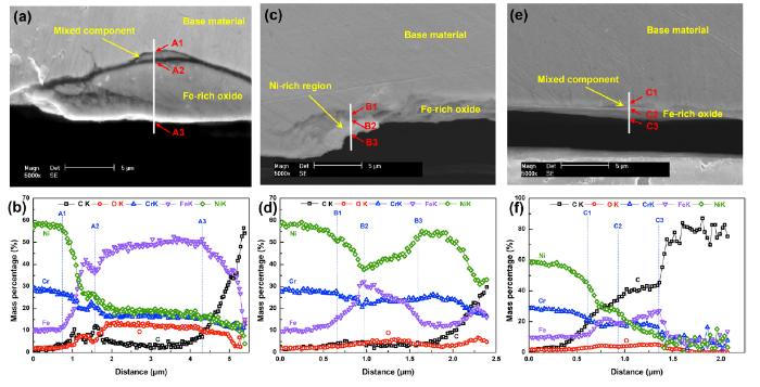
To get further information of the superficial debris layer and the subsurface structure of the worn scars, sectional samples have been prepared and analyzed by using SEM and EDS line scanning method as well, and the results are shown in Fig. 8. It can be seen from Fig. 8a, b, there is obviously a large particle stuck to the outer surface of the base material (690TT) at RT. This particle is Fe-riched and somewhat oxidized during the fretting corrosion process. The source of this Fe-riched particle is transferred from the 405 SS bar that has a high content of Fe. This kind of phenomenon is consistent with what has been found during the EDS line scanning across the worn scar (Fig. 7a, d). There is also a mixed component between the base material and the Fe-riched particle, which represents the mixture of 405 SS and 690TT during the fretting corrosion process. In addition, the stick mixture only appears at partial regions of the whole section sample which is identical to the result of surface morphology analysis. Micro-cracks with a length of ~ 3 μm are observed in the 690TT under the transferred particle.
Fig. 8 Microstructure of the cross sections of the worn scars on 690TT tested at different temperature and the corresponding EDS line scanning results: a, b for RT, c, d for 100 °C, e, f for 200 °C
As for the sample tested at 100 °C shown in Fig. 8c, d, the Fe-riched oxides distribute in-homogeneously, and its morphology is in a compacted layer form, rather than a large particle which was observed at RT. In addition, the mass percentage of Fe for the Fe-riched oxide is much lower than that of RT sample which means the generation of Fe-riched oxide at 100 °C sample is more probable from the oxidation of 690TT itself rather than from the 405 SS. There is also a mixed Ni-riched region at the outer surface to prove this viewpoint which could not exist if the Fe-riched oxide is from the 405 SS.
When the temperature reaches 200 °C (Fig. 8e, f), thin continuous Fe-riched oxide layer comes into existence. This means a steady oxide film has already existed and thus the fretting corrosion occurs between the oxide layers of both materials which lead to the results of abrasive wear shown in Fig. 6g-i.
The profile lines measured by three-dimensional surface morphology analyzer to eliminate the influence of radian of the tubes are shown in Fig. 9a. It can be found that the maximum wear depth of RT sample appears at particular regions (torn holes in Fig. 6a, b) while other regions are hardly worn which implies the wear mode is likely adhesive wear. However, the profile lines of samples which are tested separately at 100 °C and 200 °C show the continuous wear depth which means the abrasive wear is probably the main wear mode. The sample which is tested at 200 °C has the minimum wear depth while the sample tested at 100 °C has the maximum one. At some zones, they are higher than the unworn zones because of the material transferring or accumulated debris. The wear volumes and the maximum wear depths of the worn scars calculated from three-dimensional morphology data and the profile lines are shown in Fig. 9b. The wear rates at different temperature are 2.71 × 10⁻¹⁶, 6.47 × 10⁻¹⁶ and 2.11 × 10⁻¹⁶ Pa-1, respectively, which are calculated using the same method in Ref. [14]. It is obvious that the sample at 100 °C has the highest wear rate while the sample at 200 °C has the lowest one.
Fig. 9 Cross-sectional profiles a, wear volumes and maximum wear depths b of the worn scars on 690TT tubes tested at different temperature in pure water
According to the above studies, including the COFs, the worn scar morphologies (both surface and cross section) and the corresponding chemical composition distributions, it can be affirmed that the fretting corrosion behavior is vitally affected by the environmental temperature.
Firstly, when the temperature increases, the contacted area broadens and hence the maximum contact stress decreases. Based on the Hertz’s contact theory, for the tube-plate contacted mode, b, which means the width of the contacted area, conforms to the following formula [27]:
$b^{2} = \frac{4}{\pi }R_{0} (k_{1} + k_{2} )P$ (1)
where P is the normal force (40 N), R0 is the radius of the tube, k1 and k2 are the coefficients of mechanical properties of different contacted bodies. The value of k satisfies the following formula:
$k = \frac{{1 - \mu^{2} }}{E}$ (2)
where E is the Young’s modulus and μ is the Poisson’s ratio. At the initial contact condition, the maximum contact stress p0, which is the contact stress at the center region, conforms to the following formula:
$p_{0} = \frac{2P}{\pi b}$ (3)
It is reported that the Young’s modulus of both materials sharply decreases with the increase in temperature while the Poisson’s ratio changes slightly [28], thus the coefficient k decrease as shown in Eq. (2). The decrease in k of both materials results in the broadening of the contact area as well as the value of b increases due to Eq. (1). The calculated results of the width b of the contacted area and the maximum contact stress p0 at different temperatures are listed in Table 3. The calculated results are identical to the surface morphology shown in Fig. 5 although the widths of real worn scars are far wider than the theoretically calculated results. This is probably because the contact mode changes from line-contact to the plate-contact during the long-term fretting process. And it is well known that the adhesive wear occurs where the partial stress concentrates. And as the contact area broadens with the increase in temperature, the contact stress decreases due to Eq. (3). Thus the adhesive wear preferably happens at low temperature which is confirmed by the results in Figs. 5, 6 where adhesive wear mainly appears for the sample tested at RT and rarely occurs at high temperature.
Secondly, the corrosion behavior of the mated materials plays an important role during fretting corrosion process as well. At room temperature, the original thin film formed on the 690TT tube can be easily damaged by the fretting wear and a new stable thin film between the mated material is difficult to be formed due to the low temperature, the very low DO content (< 5 μg/L) and the continuous fretting, which was proved by the SEM images in Fig. 6 and the EDS line scanning in Fig. 7. As a result, direct metal-to-metal contact occurs and adhesion or weld happens between the mated materials under the high contact stress. After certain fretting cycles, cracks initiates and propagates in the metals (Fig. 8a) and finally the torn hole forms.
As temperature increases, oxidizing increases on the 690TT when the temperature is lower than 250 °C [29]. However, stable and protective oxide film on the nickel-based alloy and stainless steel can only be formed at a temperature of 200 °C or higher. As a result, the oxide film formed at 100 °C is weakly protective which is easy to be worn away [30]. Once the oxide film is removed away, fresh bare metal will expose directly to the water and then oxidation occurs again quickly. The relationship between the friction wear and the corrosion behavior in fretting corrosion procedure has been discussed in detail [26]. In the 100 °C pure water in this study, it is doubtless that the friction wear promotes corrosion and in turn the corrosion promotes the friction wear. That is why the worn scar at 100 °C is the deepest. The debris is ejected out the scar and accumulates at the crevice area. Even though the oxide film at the worn scar zone is non-protective, it prevents direct metal-to-metal contact which could cause the material transferring in the fretting process, as is proved in Fig. 7e.
When the temperature increases to 200 °C, the whole 690TT surface will be covered by a stable dual-layered oxide film which is composed of a Cr-rich inner layer and a Fe-riched outer layer [20, 31]. Even at the worn scar zone, the oxide film formed on 690TT during the fretting wear test still has a multilayer structure where the inner layer is composed of Cr-riched oxides while the outer layer is composed of tribolayer (small amount of Cr2O3 and Fe3O4) and Fe-riched spinal oxides [32]. Though no obvious Cr-riched inner layer has been observed in EDS line scanning results (Fig. 8f) due to the low resolution of the EDS and the very thin thickness of the inner layer of nanometer scale [33], obvious Fe-riched oxide layer is found. This oxide film and newly formed debris will be mixed, ground and compacted, forming a debris layer between contacted samples under the applied normal force in the fretting corrosion process. This debris layer can affect the fretting procedure in various ways. It plays a role in lubricant and weakens the wear. The debris layer makes the contact mode change from two-body function to three-body function. The relative sliding occurs between the debris layers of the friction pair instead of adhesion, and then wear debris exists and moves reciprocally which means the abrasive wear becomes the main wear mechanism. Material transferring will not happen at this condition. In addition, the steady debris layer also has higher hardness and abrasive resistance compared to the initial oxide films after being compacted and thus the degree of wear could be reduced enormously. And this is the reason why the 690TT has the highest fretting wear resistance at 200 °C.
Thirdly, the crevice width between the contacted materials at the edge area is < 200 μm and at this condition, crevice corrosion will happen. According to the research by Chen et al., severe crevice corrosion occurred on 304 SS when the crevice width is 125 μm or 250 μm, but crevice corrosion hardly took place when the width of crevice reached to 500 μm [34]. From Fig. 5, it is obvious that crevice corrosion becomes more severe with the increase in temperature. Crevice corrosion at 200 °C can promote the formation of the compacted debris layer and hence improve the wear resistance.
The cross-sectional microstructure of the worn scar formed at RT is studied by EBSD. Figure 10 shows the inverse pole figure (IPF, Fig. 10a), grain boundary character distribution (GBCD, Fig. 10b), kernel average misorientation (KAM, Fig. 10c) of 690TT base metal just under the wear scar. The nano-grain sized tribologically transformed structure (TTS) is found which is consistent with the previous studies [26, 35]. In addition, a general deformation layer (GDL) where lots of slips whose directions are about 45° to the vibration direction is observed under the TTS. What’s more, the slips have passed through the coincidence site lattice boundaries (the red boundaries in Fig. 10b). KAM is an average value of the misorientations of a point to its all neighboring points. It can reveal the residual strain level in the material. In this study, red means the maximum residual strain in the materials while blue demonstrates the minimum residual strain value. It can be observed that the residual strain concentrates at the GDL and along the deformation slips.
Fig. 10 EBSD observation results of the cross section of the worn scar on 690TT tube tested at RT in pure water: a IPF, b grain boundary type distribution and c KAM distribution
As a result, during the fretting wear process, abrasion is not the only damage, microstructure changes, including nano-grain layer, deformation slips with high residual strain concentration and even micro-cracks will also have a detrimental effect to the service performance of the heat exchanger tubes in NPPs. For instance, high residual strain concentration and deformation slips will promote the SCC or fatigue initiation and propagation in nickel-based alloys and stainless steels in HTHP water [36, 37].
690TT tube fretting corrosion behavior has been studied which is mated with 405 SS bar. The effects of temperature on the mechanism of fretting corrosion are discussed. The conclusions can be drawn as follows:
1. The overall average of COF values descends when the temperature increases while the width of the worn scar becomes wider with the increase in temperature.
2. The severest fretting corrosion happens when the test temperature is 100 °C, the maximum wear depth is nearly three times that at RT and nearly four times that at 200 °C.
3. The wear mechanism changes with the increase in temperature. Adhesive wear is the main mechanism at RT while abrasive wear becomes a major wear mechanism at 100 °C as well as delamination. However, at 200 °C, the abrasive wear dominates and hardly any other wear mechanisms occur.
4. Wear-induced damages, including nano-grain layer, deformation slips with high residual strain concentration and micro-cracks, may have detrimental effects on the service performance of the heat exchanger tubes in NPPs.
This work is supported by the National Natural Science Foundation of China (No. 51771211), the Large-scale advanced PWR major projects (No. 2017ZX06002006), the Liaoning Provincial Natural Science Foundation of China (No. 20180540076), and the open-ended fund of the CAS Key laboratory of Nuclear Materials and Safety Assessment (Institute of Metal Research, Chinese Academy of Sciences, China) (Nos. 2019NMSAKF02 and 2017NMSAKF04). The authors are grateful for the help of 3D surface morphology analysis from Dr. Hui Feng at IMR, CAS.
The authors have declared that no competing interests exist.

 WeChat
/
| 〈 |
|
〉 |


