Wear Resistance of Two Nanostructural Bainitic Steels with Different Amounts of Mn and Ni
[Saman Ahmadi Miab1 , Behzad Avishan2  , Sasan Yazdani
1 ]
, Sasan Yazdani|
|


Extremely valuable mechanical properties in combination with acceptable wear resistance can make nanostructural bainitic steels to be used extensively in different engineering and tribological applications. However, it is critical to characterize the contributed factors to investigate the wear response of these high-strength materials. This work aims to study the wear behavior of two nanostructural bainitic steels with different amount of austenite stabilizer elements Mn and Ni. For this purpose, wear resistances of the materials were evaluated using the pin-on-disk method. The results indicated that the hardness of the sample is a critical factor affecting the tribological behavior, and the volume fraction and morphology of high-carbon retained austenite are also of considerable importance. It has also been demonstrated that transformation-induced plasticity effect during the wear test and oxide formation at worn surfaces are critical factors.
It is obvious that it is important to achieve steel products with good balance of primary mechanical properties. In this regard, high-strength steels have been evaluated in different studies to consider how their microstructural features affect the resultant strength and ductility [1, 2, 3, 4]. However, it also seems to be critical to consider their wear resistance to improve the efficiency. Given that improved wear resistance in carbide-free bainitic steels has been approved already by some researchers [5, 6, 7, 8, 9, 10], their new generations known as strong nanostructural bainitic steels are suitable alternatives to be used in different industrial applications due to their unique microstructural features. Low austempering temperatures of about 200-300 ° C result in nanoscaled bainitic subunits and austenite films both of only 20-100 nm thicknesses separated with austenite microblocks in this group of high-strength steels [11, 12, 13, 14, 15, 16, 17, 18]. By adding about 1.5 wt% silicon, the carbide precipitation will be prevented and the austenite can be made to be enriched with carbon stabilizing the retained austenite at room temperature [19]. These microstructural characteristics can satisfy the extremely valuable combinations of mechanical properties in different engineering applications [20, 21, 22]. Ultimate tensile strength (UTS) of 1600-2500 MPa, hardness of 500-700 HV and toughness of 40-120 MPa m1/2 in combination with a suitable wear resistance can be used in different industrial sectors to replace expensive engineering metallic products with nanostructured bainitic steels.
Some researches confirmed that the acceptable wear resistances of nanobainite are available. Garcia-Mateo et al. [23] studied the industrialization potential of nanostructural bainitic steels considering their tribological behavior and test results which supported the idea of acceptable wear performance of these engineering materials. In a similar work by Sourmail et al. [24], the exceptional potential of low-temperature high-silicon steels for wear applications were proposed. Yang et al. [25] reported that the sliding wear resistance of nanostructural bainitic steel was nearly 20-50% more than that of quenched and tempered samples. Wang et al. [26] illustrated that such a microstructure had a superior wear resistance comparing with ordinary quenched and tempered bearing steels based on its microstructure behavior during straining. Leiro et al. [27] clarified that nanostructural bainite exhibited significantly lower wear rate comparing with ordinary carbide-free bainitic steels. Bakshi et al. [28] showed that modifying the microstructure in order to gain fine and more stable austenite could further reduce the wear rate in nanostructural bainitic steels. A research by Zhang et al. [29] reported the excellent wear performance of low-temperature bainite obtained at surface layer of carburized steel.
High hardness value of nanobainite is an important factor when considering its wear performance. But it is critical to note that the microstructural characteristics and the volume fraction of the microstructural constituents are both of substantial importance which must be considered carefully in evaluating the wear resistance of these super strong steels. Because the soft and ductile retained austenite transforms to hard martensite during the wear test, the volume fraction and morphology of retained austenite and the transformation-induced plasticity effect (TRIP effect) seem to be detrimental factors influencing their wear performance. On the other hand, TRIP effect is directly related to the mechanical stability of retained austenite which has been studied before in more detail [12]. It has been shown that moderately stable retained austenite results in an effective TRIP effect because austenite transforms to martensite more steadily during straining the sample which could enhance strength and ductility properties simultaneously. This seems to be also important during wear performance evaluations.
This article aims to study the wear performance of two nanostructural bainitic steels with different contents of austenite stabilizers Ni and Mn after austempering at 300 ° C to explore their wear behavior based on their primary microstructural differences and further microstructural evolutions during the wear test. Precise evaluations have been conducted considering the morphology and volume fraction of phases present within the microstructure and also the TRIP effect occurrence during pin-on-disk wear test method.
The chemical compositions of steels 1 and 2 are given in Table 1, which were designed based on thermodynamic theories described elsewhere [30] using MUCG 83 thermodynamic software [31]. The chemical compositions of both steels were almost similar except that Mn was partially replaced by Ni in steel 2, where both Mn and Ni are well known as austenite stabilizers at room temperature. Steels were designed to have almost the same T0 and TTT diagrams [30, 32].
| Table 1 Chemical compositions of the two steels (in wt%) |
High amount of C content in both steels is a guarantee to decrease both Bs and Ms, and therefore, it is possible to gain bainite at lower temperature. It can also increase the strength of the parent austenite which is a determining factor in refining the final microstructure. Steels were cast in an induction furnace under inert gas atmosphere, electroslag remelted, homogenized at 1200 ° C for 2 h and hot rolled to sheets of 18 mm in thicknesses. All samples for microstructural examinations, X-ray diffraction, hardness, impact and tensile tests and wear tests, were cut and prepared from the hot-rolled sheets. Samples were austenitized in salt bath furnaces at 950 ° C for 25 min and rapidly quenched for austempering in another 300 ° C salt bath furnace for 7 h. The austempering temperature was well above the experimentally determined Ms, and the selected austempering time was to ensure the completion of bainite transformation.
Samples for metallographic observation were ground and polished following the standard procedures after heat treatment. A 1% nital etching solution was used to reveal bainitic microstructure. Primary microstructural evaluations were conducted on Olympus PMG3™ optical microscope. Transmission electron microscope (TEM) was used for extensive microstructural characterizations, and different micrographs were used to determine the size of the microstructural constituents, i.e., bainitic ferrite and austenite films, using the mean line intercept method [33, 34]. TEM specimens were sliced from 3-mm-diameter rods of heat-treated materials, mechanically thinned to 0.06 mm and then twin-jet electrolytically polished to perforation using a mixture of 5% perchloric acid, 25% glycerol and 70% ethanol at -6 ° C at 45 V. Samples were studied on a JEM-2010™ transmission electron microscope operating at 200 kV.
The volume fraction of retained austenite (Vγ ) and its carbon content (Cγ ) were determined using X-ray diffraction (XRD) analysis on a Bruker-Axs D8 Advance™ X-ray diffractometer with monochromated CuKα radiation at 40 kV and 40 mA. The volume fractions of retained austenite and bainitic ferrite were calculated from the integrated intensities of (200), (220) and (311) austenite peaks, and those of (200), (211) and (220) peaks of ferrite [35]. Austenite carbon content was determined using well-known Dyson and Holmes’ equation [36].
Pin-on-disk wear tests were conducted according to ASTM G99 standard on a wear test machine especially built for laboratory use. Tests were conducted under a load of 40 N and speed of 0.3 m/s without any lubricant, using heat-treated cylindrical pins of 5 mm diameter which were cut from primary rolled sheets. The abrasive disk was AISI 52100 bearing steel with 130 mm in diameter, which was austenitized at 845 ° C for 45 min, oil quenched and subsequently tempered at 150 ° C for 30 min to have a final hardness of 800 HV. The wear rates of samples were determined based on the weight loss at distances of 250, 500, 750 and 1000 m and new sets of samples were used for each run in order to minimize the test errors. Cam Scan MV-2300™ scanning electron microscope (SEM) was also used to investigate the worn surfaces of the samples. Specimens were cleaned using an ultrasonic cleaner before and after the tests.
HV hardness (294 N load) was measured, and the results were obtained corresponding to an average of at least 3 values. Besides, microhardness tests were conducted along the cross sections of the worn samples to analyze the depth of the deformed layer. Impact energies of the materials were evaluated at room temperature using 10 mm × 10 mm × 55 mm notched samples. The uniform elongation was measured after conducting tensile tests at room temperature using flat test samples with 9.8 mm gage lengths cut from heat-treated materials according to the JIS Z2201 standard.
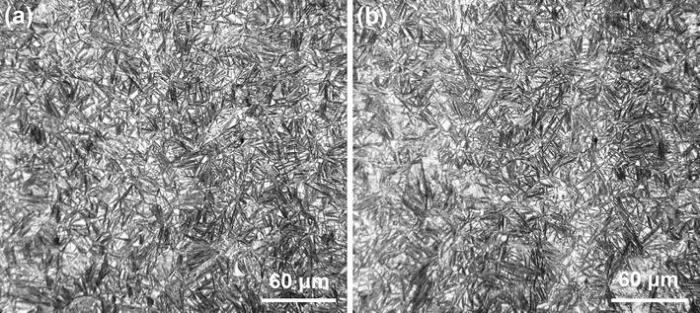
Optical micrographs of both steels in Fig. 1 and corresponding XRD refinements in Table 2 demonstrate that the microstructures are essentially composed of only two phases, bainitic ferrites and carbon-enriched retained austenites. Bainitic transformation starts with paraequilibrium nucleation of ferrite subunits from primary austenite grain boundaries and proceeds by shear growth. The resulting microstructure is bainitic sheaves (dark features) which are aggregates of nanoscale bainitic subunits and austenite films of same crystallographic orientations where different sheaves are separated with austenite microblocks (light features).
 | Fig. 1 Optical micrographs of steel 1 a and steel 2 b |
| Table 2 Volume fractions of bainitic ferrite (Vα ), austenite (Vγ ), austenite films (Vγ f), austenite blocks (Vγ b), austenite carbon content (Cγ ), sub unit thickness (tα b) and hardness |
XRD refinements confirm that steel 2 contains higher volume fraction of retained austenite within the microstructure. This is reasonable when considering the higher bainite nucleation driving forces of Δ G = -2598 J/mol for steel 1 comparing with Δ G = -2575 J/mol for steel 2 according to the MUCG 83 thermodynamic software calculation [31]. On the other hand, according to the work of Bhadeshia and Edmonds [37], about 15% of the volume contained within the boundaries of a bainite sheaf consists of retained austenite films interspersed with bainitic ferrite subunits. Although the volume fractions of the austenite films are almost the same in both steels, there is higher amount of blocky austenite in steel 2. Higher driving force for bainite nucleation and consequently higher volume fraction of bainitic sheaves in steel 1 result in consumption of more primary austenite. Therefore, lower volume fraction of high-carbon retained austenite will remain stable within the microstructure. The carbon content of the austenite is a critical factor influencing its stability, and it is a natural consequence of bainite transformation mechanism described above. Once bainite stops growing, the excess C trapped within the bainitic ferrites diffuses to the parent austenite. However, austenite blocks are poor in carbon especially in center, so it seems to be critical to replace it with more stable filmy morphology. The results in Table 2 demonstrate that both steels have almost the same C concentration. However, higher amounts of C are expected to be solved in austenite films comparing with austenite blocks.
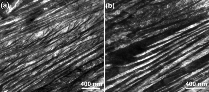
It is critical to characterize the scale of the microstructures. TEM micrographs in Fig. 2 demonstrated that each sheaf contains bainitic subunits and austenite films, with almost the same thicknesses in nanoscale. TEM micrographs emphasize the nanoscale of the bainitic subunits with almost (63 ± 3) and (71 ± 2) nm in thicknesses for steel 1 and steel 2, respectively. The strength of high-carbon retained austenite is the main factor influencing the bainite subunits thicknesses. The elements such as Ni and Mn have a detrimental strengthening ability in solid solution, and Mn has a stronger influence [38, 39], such that finer subunits in steel 1 can be obtained, as seen in Table 2. It is important to note that detailed TEM evaluations failed to reveal any carbide precipitations due to the presence of more than 1.5 wt% Si which delays the precipitation of cementite.
 | Fig. 2 TEM micrographs of steel 1 a and steel 2 b |
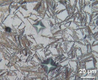
It is important to consider the hardness of a material when talking about its wear performance. In this regard, the volume fraction of bainitic ferrites and the scale of the microstructural constituents are the main contributions influencing the hardness in nanostructural bainite. Higher volume fraction of thinner bainitic subunits can further increase the hardness. However, this is in contradiction with the results in Table 2 comparing both steels. It can be seen that steel 2 is harder than steel 1 contrary to its lower volume fraction of bainitic ferrite and thicker subunits. This can be rationalized by microhardness tests conducted to determine the hardness of big blocks in the microstructure according to Fig. 3. Microhardness test results showed that bigger blocky regions had a hardness of about 665 HV in some places those of which were higher than that of ordinary hardness of 440 HV of the microstructure. This can be directly explained based on the theory proposed by Kammouni et al. [40], claiming that retained austenite with carbon content of < 0.5% is not thermally stable and about 1 wt% of carbon is mandatory in order to resist the transformation of austenite to martensite during cooling to room temperature from transformation temperature. In fact, XRD is a bulk analysis method and therefore it cannot disclose the large variations of austenite carbon content from region to region. Thus, the calculated carbon contents in Table 2 cover the average of the carbon contents in both filmy and bulky austenites within the microstructure. So, it can be concluded that higher volume fraction of bigger austenite blocks which were present within the microstructure of steel 2 transformed to martensite during cooling to room temperature because they were poorer in carbon especially in center regions. This in turn could increase the hardness of the samples despite the lower volume fraction of bainitic ferrites and thicker subunits.
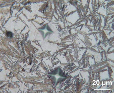 | Fig. 3 Micrograph of the microhardness indents within the microstructure of steel 2 after austempering at 300 ° C |
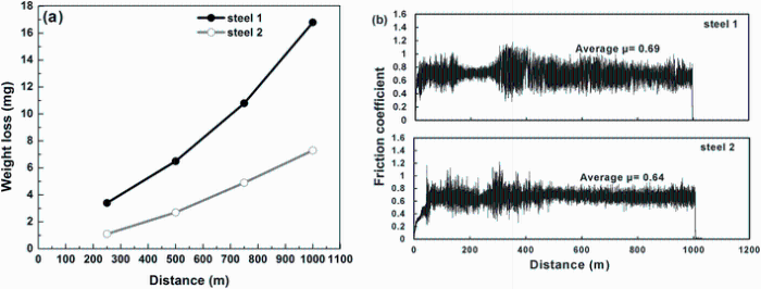
Figure 4 depicts the weight loss of the samples at different wear distances and corresponding friction coefficient profiles. It is evident that weight loss is increasing with increasing the wear distance in both steels being more severe at any identical wear distances in steel 1. Also, the mean friction coefficient value is smaller in steel 2 approving its better wear performance. Kankanala et al. [9] and Leiro et al. [10] reported that friction coefficient profiles are the useful criterions in order to discuss the tribological behavior of steels, during their study on wear performance of carbide-free bainite under dry rolling/sliding conditions. Similarly, same method has been used in this study to evaluate the wear behavior of steels.
According to the works of Kankanala et al. [9] and Leiro et al. [10], friction coefficient profiles can be divided into two regions being typical mostly for dry contacts, i.e., running-in and steady-state regions, whereas the initial surface roughness of the test materials is detrimental factor explaining the running-in region. A higher initial surface roughness results in a longer running-in period due to the longer time needed for big asperities to be worn off [9, 10]. According to Fig. 4, the friction coefficients in both steels in this study increase during running-in stage after which it reaches a steady state. Reported friction coefficients on the illustrations are the average values along this region. A higher friction coefficient value means a more severe contact between surfaces which in turn increases the stress and thus the weight loss of the samples.
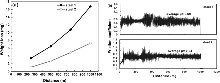 | Fig. 4 Fig. 4Weight loss results a and friction coefficients b of steel 1 and steel 2 |
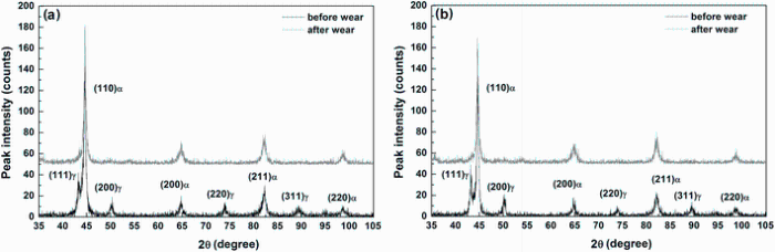
Several factors can detrimentally influence the wear performance of the material, for example, the initial load, wear test conditions (cycles, areas of contact and etc.) and wear distance, those of which were all kept constant, and they were identical for conducted tests in this study. However, initial hardness, volume fraction and morphology of the present phases within the microstructure and strain-induced martensitic transformation must also be considered precisely. Samples with a higher initial hardness can further resist to be worn off. This can primarily explain the superior wear resistance in steel 2 according to its higher hardness as described before. On the other hand, considering the volume fraction of high-carbon retained austenite present within the microstructure and also considering austenite to martensite transformation, comparing XRD profiles obtained from worn surfaces with those of raw materials in Fig. 5 indicates that there is almost no austenite remaining at the end of the wear tests in both steels. This means that austenite completely transformed to martensite by applying strain during wear tests in both set of samples similar to those observed previously [9, 10]. This in turn could increase the hardness at the surface of the test specimens which consequently further resists the material removal and weight loss [41]. So it is logical to expect a better wear performance in steel 2 due to its higher volume fraction of retained austenite and therefore higher volume fraction of martensite formed at the surface of the specimen due to the massive plastic deformation which further increased the hardness of the material.
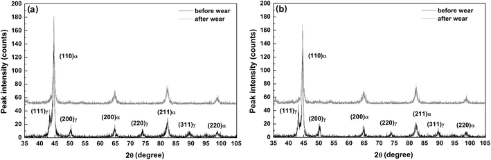 | Fig. 5 XRD profiles of steel 1 a and steel 2 b before and after wear test |
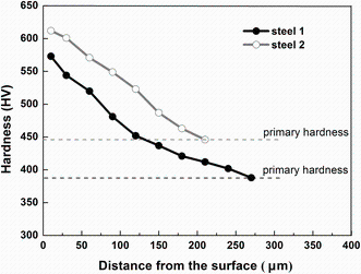
Microhardness profiles along the cross section of the samples in Fig. 6 confirm this idea. Graphs show that there is a significant hardening at the surface in both cases which is the result of both strain hardening and TRIP effect [9, 10]. Besides, hardness at the surface and along the cross section of steel 2 is always above the values obtained for steel 1, this is because of the higher bulk hardness and higher martensite content formation at the surface of the material. The deformed subsurface layer is deeper in steel 1 which can be attributed to lower hardness of the worn surface. Worn surface is harder in steel 2, which consequently inhibits the force transferring deeper. However, steel 1 undergoes plastic deformation deeper into the bulk and consequently a thicker hardened layer can be achieved.
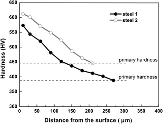 | Fig. 6 Hardness profiles for steel 1 and steel 2 |
In Fig. 4, weight loss of steel 1 is much more severe than that of steel 2 and also weight loss differences at later wear stages are much bigger. This can be explained due to the rate of austenite to martensite transformation (TRIP effect). It seems that austenite transforms to martensite more gradually in steel 2 which consequently further reduces the wear rate. This can be related to its more effective TRIP effect comparing with that of steels 1. If austenite is mechanically more stable, it transforms to martensite in a more progressive manner and results in a more effective TRIP effect which has been described previously [12]. Because Mn and Ni are known to significantly improve the austenite mechanical stability and considering Ni being more effective comparing with Mn [42], it is logical to achieve more effective TRIP effect and consequently better wear performance in steel 2. The constrain exerted to austenite by surrounding martensite which is present within the microstructure of steel 2 in bigger blocky regions, as described previously, can also be an explanation for the moderate austenite to martensite transformation. This martensite introduces high density of dislocations in the microstructure and restricts the motion of glissile interface of austenite-martensite and volume increase during the TRIP effect.
It is also important to note that an effective TRIP effect can enhance the ductility and toughness in multiphase steels containing high-carbon retained austenite within their microstructure. On the other hand, Leiro et al. [27] demonstrated that better toughness properties lead to better wear resistance in nanostructural bainitic steels. This is also applicable in this study where higher amount of retained austenite and more effective TRIP effect resulted in higher values of impact energy and elongation in steel 2. Results indicate that impact energies of 19 and 24 J and uniform elongations of 21 and 26% could be achieved at room temperature for steel 1 and steel 2, respectively. Consequently, it is rational that steel 2 withstands more plastic deformation during the wear test improving the wear performance according to its enhanced toughness and ductility properties.
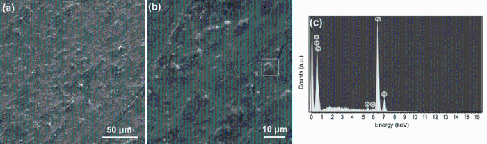
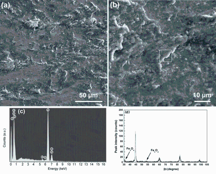
Figures 7 and 8 show the SEM micrographs of worn surfaces of the materials in which the occurrence of internal plastic flow with entrapment of oxide particles are evident. Plastic flows are more distinguishable in steel 2 according to the higher volume fraction of the retained austenite, improved mechanical stability of austenite, more gradual TRIP effect and therefore higher toughness values. Oxide formation has been confirmed by EDX, the fraction and connectivity of which is more evident in steel 2. This has been also confirmed by XRD analysis where oxide peaks were identified as it has been demonstrated in Fig. 8d. These oxide layers have a protective role, and consequently they can decrease the wear rate of the samples. This is another evidence to make it more logical to gain a lower wear rate and better wear performance in steel 2.
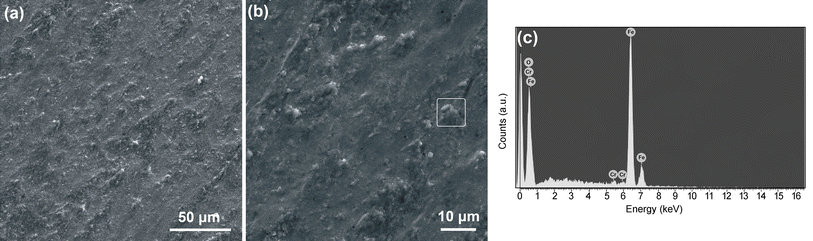 | Fig. 7 SEM micrographs of the worn surfaces of steel 1 a, b, EDX analysis of the marked region in b, c |
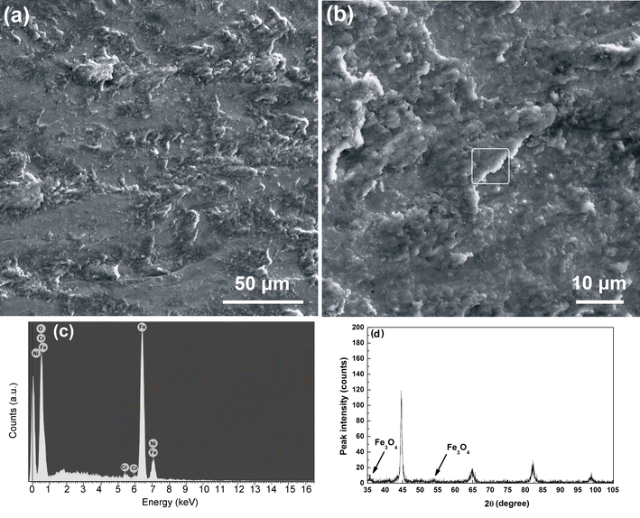 | Fig. 8 SEM micrographs of the worn surfaces of steel 2 a, b, EDX analysis of the marked region in b, c and the corresponding XRD profile d |
The tribological behaviors of two nanostructural bainitic steels were studied considering different parameters affecting their wear performance using pin-on-disk method. It has been shown that transformation of bigger austenite microblocks within the microstructure to martensite during cooling to the room temperature increased the primary hardness of the steel. Higher hardness of the material resisted the material removal and consequently improved the wear performance. However, hardness could not be the only criterion when discussing the wear behavior. An effective TRIP effect at the surface of the material could further increase the hardness of the surface and consequently enhance the wear resistance. Moreover, it has been shown that enhanced toughness and ductility properties could further promote the wear performance of the material and hard oxide particles formed at the surface of the specimens could take a protective role in wear test.
Authors are grateful to Sahand University of Technology, Tabriz, Iran, for supporting and providing the research facilities. Prof. T.S. Wang from State Key Laboratory of Metastable Materials Science and Technology, Yanshan University, Qinhuangdao, China, is also gratefully acknowledged for helping with TEM works.
The authors have declared that no competing interests exist.
| [1] |
|
| [2] |
|
| [3] |
|
| [4] |
|
| [5] |
|
| [6] |
|
| [7] |
|
| [8] |
|
| [9] |
|
| [10] |
|
| [11] |
|
| [12] |
|
| [13] |
|
| [14] |
|
| [15] |
|
| [16] |
|
| [17] |
|
| [18] |
|
| [19] |
|
| [20] |
|
| [21] |
|
| [22] |
|
| [23] |
|
| [24] |
|
| [25] |
|
| [26] |
|
| [27] |
|
| [28] |
|
| [29] |
|
| [30] |
|
| [31] |
|
| [32] |
|
| [33] |
|
| [34] |
|
| [35] |
|
| [36] |
|
| [37] |
|
| [38] |
|
| [39] |
|
| [40] |
|
| [41] |
|
| [42] |
|