Mechanical and Metallurgical Characterization of HSLA X70 Welded Pipeline Steel Subjected to Successive Repairs
1 Research Center in Industrial Technologies (CRTI),P.O.Box 64, 16014 Cheraga, Algeria
2 Laboratoire des Ae´ronefs, Universite´ de Blida1, 09000 Blida,Algeria
3 LGSDS, Ecole Nationale Polytechnique, El Harrach, 16200 Algiers, Algeria
4 LTSM, Universite´ de Blida1, 09000 Blida, Algeria
5 ICMMO/SP2M, Bat 410, Universite´ Paris-Sud 11, 91405 Orsay Cedex, France;
CorrespondingAuthor: Bouzid Maamache,
b.maamache@csc.dz
1 IntroductionThe assembly techniques of metallic materials are continually evolving. In order to achieve a perfect continuity between the joined materials, it is important to control the weld and repair any defects. In practice, the technical and economical parameters obligate the supervisor to stamp out locally the defects in order to avoid the cutting or the total rejection of the weld joint. According to DNV-OS-F101 standard [1], it is stated that weld seams can be repaired twice at most in the same area. Thus, it is somehow a limiting condition in the welded assembly using shielded metal arc welding process (SMAW), namely for pipeline joining. However, in the API 1104 standards [2] and the ASME IX section [3], nothing was mentioned concerning weld seams repair.
Among the wide range of pipeline steels, the X70 steel has been widely used for crude oil and natural gas transportation over long distances under high pressure [4]. Hence, it should exhibit good toughness all over its different parts even at low temperature [5]. It is noted that the weld repair operations induce several thermal cycles, generating a variation in the heat-affected zone (HAZ) extent, and influence its microstructure as well as its mechanical behavior.
Di et al. [6] published that short cooling time reduced the toughness of the intercritical HAZ (ICHAZ). This is related to the fraction area of the martensite-austenite (M-A) constituent. Qiu et al. [7] reported that in the coarse-grained HAZ (CGHAZ), coarse grains lead to a decrease in the crack propagation energy. However, it is asserted that the high density of high misorientation grain boundaries in the fine-grained HAZ (FGHAZ) inhibits the crack propagation and improves its toughness.
Currently, there are a few studies related to the influence of successive weld repairs on the mechanical behavior of X70 steel weld joints. Vega et al. [8] investigated the X52 weld repairs and found a retention of tensile strength with a significant decrease in toughness at the fusion line zone (FLZ). Aghaali et al. [9] and Tiwari et al. [10] noted that after the first weld repair, both the yield strength and the ultimate tensile strength decrease with a significant reduction in Charpy-V impact resistance as a function of weld repair number. The most interesting remark was made by Lai and Fong [11], who stated that the apparent lowering in the fracture resistance of the weld repair not only is attributed to the microstructural change in the HAZ, but also is caused by the presence of the defects.
Jang et al. [12] revealed the importance of the V-notch position on the energy absorbed in the HAZ via experimental and numerical studies. They reported that Charpy-V tests have been performed to evaluate the effect of the different notch positions on the failure behavior in the HAZ in order to determine the best performance in sour environments. Several approaches have been investigated to study the residual stresses induced by fatigue test using X-ray diffraction (XRD) [13]. Likewise, Tsuji et al. [14] have adopted the same technique to evaluate the distribution of residual stresses in welds accompanied by phase transformation. Subsequently, residual stresses caused by the weld thermal cycles could be determined by employing XRD measurement as studied by Hempel et al. [15]. Chen et al. [16] claimed that the addition of alloying elements has a significant influence on the microstructural and mechanical properties, as it improves both the strength and the toughness of the HAZ.
Yi et al. [17] noted that the mechanical properties of the HAZ decreased progressively when the weld repair number was increased. However, Nascimento and Voorwald [18] mentioned that the weld repair effectively delayed the crack propagation along the new HAZ, i.e., the repetitive repairs are beneficial to the HAZ properties.
So far, the effect of the microstructural parameters on the mechanical properties of this zone is not sufficiently highlighted in the literature. In the present work, the relationship between the microstructural parameters and the mechanical properties of the welded and re-welded API 5L-X70 steel was investigated and the vulnerability of the HAZ induced by successive repairs was mainly focused. Our aim is to determine, on the one hand, the effect of successive repairs on the microstructure evolution using XRD with Rietveld refinement method in order to estimate the dislocation density and the crystallite size. And, on the other hand, we attempt to evaluate the mechanical behavior of each repair by tensile and Charpy-V tests.
2 Materials and MethodsThe material used in this work was an X70 HSLA steel. It was received in the form of pipelines 203.2 mm in diameter and 12.7 mm in thickness. Successive weld repair operations were conducted on an as-welded (Wo) pipeline by the submerged arc welding (SMAW) process using E6010 and E7010 electrodes. The chemical compositions of the base metal and weld metal (WM) are summarized in Table 1, and the welding parameters are given in Table 2.
Table 1
Table 1
 Table 1 Chemical composition of the API 5L X70 steel pipe| Elements (%) | Ceq | C | Si | Mn | P | S | Cr | Mo | Ni | Nb | Ti | V | Cu |
|---|
| Base metal | 0.36 | 0.073 | 0.08 | 1.65 | 0.037 | < 0.01 | - | 0.006 | 0.044 | 0.061 | 0.01 | < 0.01 | 0.123 | | Weld metal | - | 0.1 | 0.48 | 0.2 | 0.02 | 0.017 | 0.037 | 0.039 | 0.35 | - | - | - | - |
| Table 1 Chemical composition of the API 5L X70 steel pipe |
Table 2
Table 2
Table 2 Parameters of welding process| Layers | Root | Filling | Cap |
|---|
| Welding process | SMAW | SMAW | SMAW | | Welding position | 5G | 5G | 5G | | Current and polarity | DC (-) | DC (+) | DC (+) | | Filler metal | E6010 | E7010 | E7010 | | Φ Electrode (mm) | 3.25 | 4 | 4 | | Amp. range (A) | 90-110 | 120-130 | 120-130 | | Volt. range (V) | 25-35 | 25-38 | 25-38 |
| Table 2 Parameters of welding process |
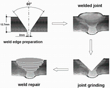
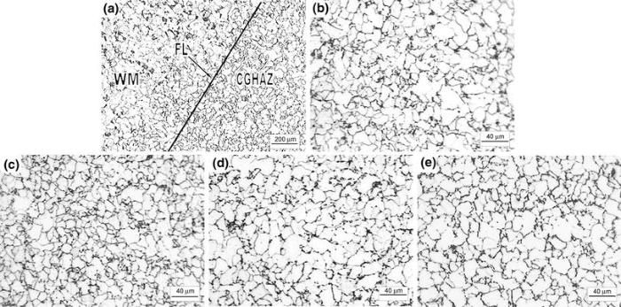
The sequences of repairs are illustrated in Fig. 1, which exemplifies how they are formed by grinding the welded joint until a certain depth to remove completely the prior weld metal, and repairing the assembly again. The weld repair operations were carried out three times on the same area. A radiographic control was conducted on the welded joint obtained from each welding operation to verify the quality of the assemblies. To identify the macro- and micrographics of the welded joints, the specimens were longitudinally cut and polished until the obtention of a reflecting surface and subsequently etched with 2% Nital solution. The XRD technique was performed to characterize the HAZ of different welded and repaired samples using a Bruker D8 diffractometer with CuKα radiation.
The crystallite size and the microstrain values were evaluated by using an isotropic model employing MAUD software (material analysis using diffraction) based on a Rietveld refinement procedure [19].
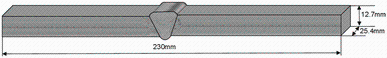
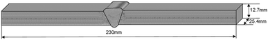
Tensile tests were conducted at room temperature, employing an INSTRON universal testing machine as standard specimens machined according to API 1004 requirements (Fig. 2).
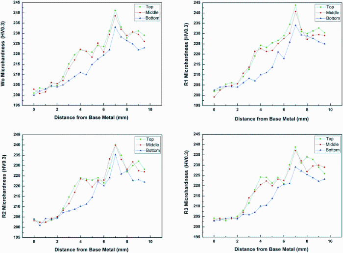
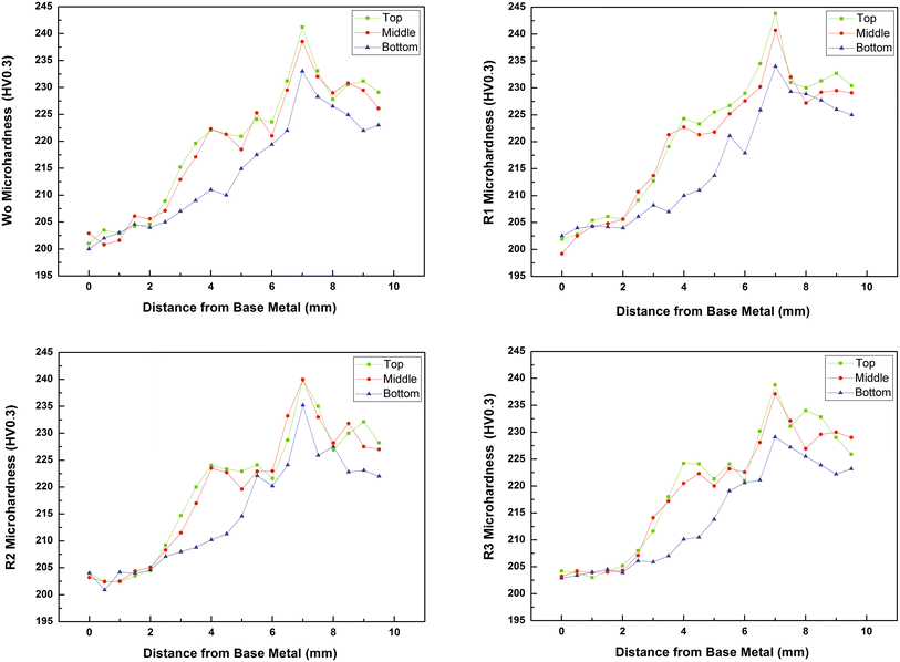
Microhardness measurements were carried out using a Buehler Ltd testing machine with a Vickers indenter under a load of 300 gf. Microhardness filiations were also conducted on the transverse sections covering the different regions of the welded joint. And three parallel profiles were made: top, middle and bottom.
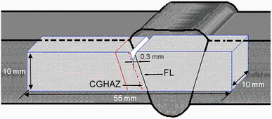
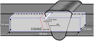
The specimens of Charpy-V test were machined with dimensions of 10 mm × 10 mm × 55 mm (Fig. 3) according to ASTM E23-09 standard [20]. To distinguish the HAZ from other parts of the welded joint, the specimens were etched by 2% Nital solution. The V-notch position of CGHAZ specimens was machined at about 0.2-0.4 mm away from the fusion line (FL) to exclude or stay away from the FGHAZ microstructure. However, since the fusion line is close to the CGHAZ, its toughness is certainly inevitable.
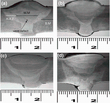
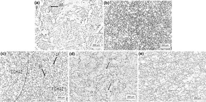
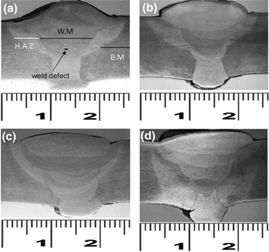
3 Results and Discussion3.1 Effect of Successive Weld Repairs on the Microstructural EvolutionFigure 4 illustrates the macrographs of the successive weld repairs. It can be seen that the HAZ extent evolves proportionally with the number of repairs due to the thermal cycles induced by the repetitive weld repairs as listed in Table 3. The results of the microstructural examination are shown in Fig. 5. As expected, the weld metal (Fig. 5a) mainly contains acicular ferrite (AF) and Widmanstä tten ferrite (WF). However, the base metal (BM) is composed of bainite (B) and acicular ferrite (AF), which are oriented in the same direction caused by the thermomechanical controlled rolling (TMCR) (Fig. 5e).
Table 3
Table 3
Table 3 Width of the heat-affected zone in each weld repair| Number of repair | Wo | R1 | R2 | R3 |
|---|
| Width of HAZ (mm) | 2-4 | 2-5 | 3-5 | 3-5 |
| Table 3 Width of the heat-affected zone in each weld repair |
The HAZ is composed of three different parts (Fig. 5c) that can be described as follows:
1. CGHAZ that contains a mixture of bainite and acicular ferrite. This part is close to the fusion line, which is formed between the recrystallization and the solidus temperatures.
2. FGHAZ formed between the recrystallization temperature and Ac3.
3. ICHAZ located nearby the BM that was exposed to a temperature above Ac1.
These different parts have been well investigated by Gao et al. [21].
The upper part of the HAZ is characterized by the presence of polygonal ferrite (PF) and brittle martensite-austenite (M-A) constituents (Fig. 5b), whereas the lower one exhibits high amount of granular bainite (GB) and polygonal ferrite as shown in Fig. 5d.
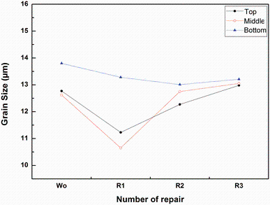
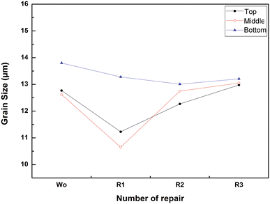
The difference observed in the microstructure of the upper, midst and lower part of the HAZ can be explained by the cumulative effect of the weld thermal cycles. As a matter of fact, during multi-pass welding, the HAZ located near the root pass is subjected to the effect of cumulative thermal cycles of the filling passes, which promotes the grain coarsening in this region. However, the top of the HAZ is characterized by finer grains due to the rapid cooling rate (Fig. 5b). Figures 6 and 7 illustrate, respectively, the evolution of the microstructure and the grain size in the HAZ as a function of the number of repairs. It is worth noting that the measurements are carried out in three different zones of the CGHAZ (top, middle and bottom) at about 200-300 µ m from the fusion line (FL).
It can be clearly seen that there is a proportional relationship: Whenever the number of repairs is higher, the grain size becomes larger. This phenomenon is related to the thermal cycle generated by the number of repairs. What should be noted is that after the first weld repair (R1) operation, the grains are finer than those of the as-welded state; in other words, their size shrinks from 12 to 10 µ m in the middle. This refinement may be attributed to the primary recrystallization and the presence of micro-alloying elements that stop the grain coarsening. Moreover, increasing the number of repairs induces multiple thermal cycles, which implies the dissolution of the micro-alloying elements and consequentially boosts the grain growth observed in the middle of the HAZ. However, a slight change in the grain size is observed in the upper parts as a function of the number of the weld repairs. These results are in good agreement with those published by Vega et al. [8] and McGaughy [22].
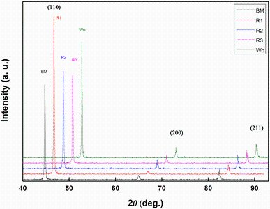
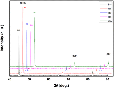
3.2 XRD Line Profile Analysis Using MAUD SoftwareFigure 8 shows the X-ray spectra of the base metal and the HAZ for each of the welded joints. The three peaks that represent the diffraction plane are (110), (200) and (211) and they exemplify the characteristics of α -Fe. The (110) is the highest peak. It corresponds to the first weld repair, whereas (200) is the lowest compared to other specimens. This orientation could be attributed to crystallographic texture, resulting from the thermomechanical history of the BM. What should be noticed is that the HAZ keeps the same microtexture (grain orientation) as the BM because the intensity of the peak (110) does not change after the successive repairs.
X-ray diffraction line profile analysis (XRDLPA) facilitates the obtention of detailed information about the mean of each of the sub-grain size, the coherent domain of diffraction (crystallite size), the internal microstrains and the related dislocation densities. Thus, a comprehensive characterization of the microstructure may be achieved most easily through the application of XRDLPA by using MAUD software based on the Rietveld refinement procedure.
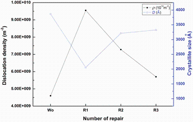
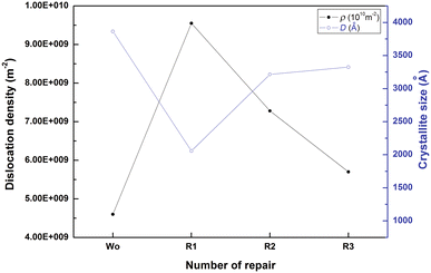
Table 4 shows that the material is under a low local strain after the welding process, which leads to minimum microstrain value [root mean square (rms)] and an important crystallite size value. Figure 9 shows clearly that, after the first weld repair operation, the strain is of high importance as it causes a decrease in the crystallite size and an increase in both the microstrain and the dislocation density. After the second repair operation (R2), an increase in the crystallite size accompanied with a decrease in the microstrain and the dislocation density of the HAZ is noticed. This can be explained by the partial relaxation of the local strain and the residual stress distribution. Because the welding process can be considered as an intense local heat treatment, it may generate severe thermal gradients resulting in a non-uniform plastic deformation. As a result, thermal misfits and local expansion can be the source of the large amounts of dislocations as the material cools. However, dislocation density and microstrain are also closely related to the straining because of the internal strains induced by the weld thermal cycles, which might explain the increase in these microstructural parameters after the first weld repair.
Table 4
Table 4
Table 4 Microstructural parameters after Rietveld refinement of base metal and HAZ of each weld repair | BM | Wo | R1 | R2 | R3 |
|---|
| a (Å ) | 2.862 | 2.864 | 2.868 | 2.867 | 2.869 | | D (Å ) | 1154.089 | 3864.485 | 2058.045 | 3215.580 | 3325.952 | | rms | 7.955 × 10⁻⁴ | 4.647 × 10⁻⁴ | 5.143 × 10⁻⁴ | 6.127 × 10⁻⁴ | 4.550 × 10⁻⁴ | | ρ (m-2) | 2.638 × 10¹⁰ | 0.460 × 10¹⁰ | 0.955 × 10¹⁰ | 0.728 × 10¹⁰ | 0.570 × 10¹⁰ |
| Table 4 Microstructural parameters after Rietveld refinement of base metal and HAZ of each weld repair |
After the second repair, an increase in crystallite size values with the decrease in dislocation density is recorded due to the recrystallization that occurs in the HAZ. These results match the earlier ones published by Zhang et al. [23] and Khereddine et al. [24].
3.3 Effect of Weld Repair on the Mechanical BehaviorThe curves showing the microhardness evolution across the as-welded and repaired joints (Fig. 10) exhibit a similar tendency. In other words, an increase in hardness values was restricted from BM [(202 ± 2) HV0.3] to the fusion line, and then a small decrease was recorded until (227 ± 3) HV0.3 in WM for the different profiles (top, middle and bottom). The hardness level of the HAZ can be attributed to the formation of AF and bainite ferrite (BF). Besides, because of the WF and BF location in the top of the weld metal (Fig. 5a), the hardness values are higher in this region compared to those recorded in the bottom. This is probably because the PF microstructure constitutes this region. These findings are in good agreement with those found by Beidokhti et al. [25].
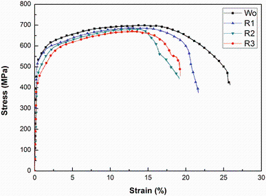
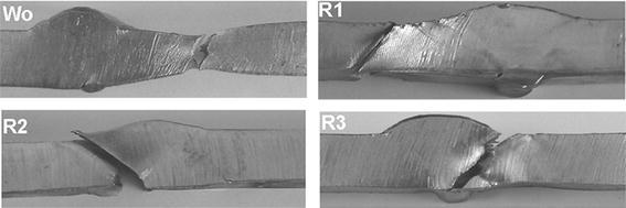
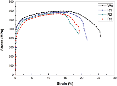
The grain refinement and the increase in the dislocation density obtained in the HAZ of the first repair enhance the hardness value. However, the grain growth recorded in the second (R2) and third weld (R3) repairs causes a decrease in hardness values, which can be related to the succession of weld thermal cycles. It is worth noting that similar findings were obtained by Vega et al. [8] and McGaughy [22]. Table 5 and Fig. 11 illustrate yield strength (YS) and tensile strength (TS) values corresponding to the as-welded and repaired joints. It can be seen that YS decreases with the increase in number of repairs. The specimens corresponding to the as-welded state, the first and the second weld repair operations satisfy the standard requirements since the failure occurred in the BM (Fig. 12). For R2, the YS value corresponds proportionally with the standards requirement, whereas the failure zone, which is located in the HAZ, can be attributed to the grain growth. However, R3 presents low YS and the lowest toughness. Hence, the third weld repair does not meet the API standard requirement. Thus, it is recommended to apply no more than two repairs in the same region of the HAZ.
Table 5
Table 5
Table 5 Result of tensile tests | Yield strength (MPa) | Tensile strength (MPa) | Strain (%) | Failure zone |
|---|
| Wo | 515 | 694 | 22.81 | Base metal | | R1 | 513 | 681 | 18.25 | Base metal | | R2 | 485 | 660 | 15.25 | HAZ | | R3 | 436 | 668 | 14.48 | HAZ |
| Table 5 Result of tensile tests |
The high values of YS and TS in the as-welded joint as well as in the first repaired joint (R1) are due to the existence of micro-alloyed elements that prevent the enlargement of the austenitic grain size through the formation of barriers at the grain joints as fine precipitations. Therefore, the decrease in YS recorded in the HAZ of R3, caused by the excessive grain growth, has an important effect on the quality of the welded assemblies. These results are supported by those published by Aghaali et al. [9].
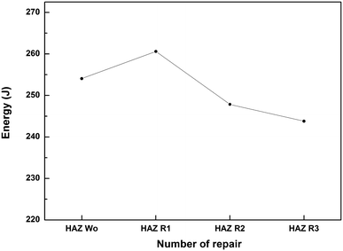
Figure 13 shows the impact tests for each welding case. The specimens corresponding to R1 absorb a high energy (260.6 J) before fracture in comparison with the as-welded state. This can be attributed to both grain refinement and high dislocation density recorded in the HAZ. In addition, a slight decrease in energy in R2 and R3 was observed (247.8 and 243.8 J, respectively). This can be related to the grain coarsening recorded in the CGHAZ in accordance with a significant decrease in the dislocation density. Moreover, the loss of toughness is due to the presence of brittle and hard constituents M-A known by their low resistance to crack as confirmed by Shin et al. [26]. Furthermore, Di et al. [6] reported that M-A constituent is distributed along the grain boundaries dividing the grains of ferrite and bainite. This implies a generation of stress concentration area, which allows a formation of microcracks at M-A and its surrounding and thus a deterioration of toughness.
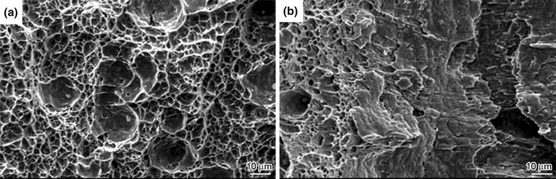
The characterization of the fracture mode of the Charpy specimens, tested at room temperature using scanning electron microscopy (SEM), is given in Fig. 13. The fracture surfaces of the as-welded joint (Fig. 14a) reveal a fully ductile fracture, whereas those corresponding to R3 (Fig. 14b) indicate a mixture of cleavage and dimples. The smallest dimples (2-6 µ m) located in the left of R3 are aggregated by several closely spaced particles that present a ductile failure. The right side exhibits a concentration of cleavage, which might be related to the formation of brittle phase M-A in the CGHAZ and the residual stresses generated by the weld thermal cycles. The area of the dimples is proportional to the number of repairs; the fracture surface of the as-welded joint presents large and small dimples, which depend on the state of stresses present in the microstructures. In addition, R1 presents very small dimples, which are compatible with grains refinement observed in the microstructure.
4 Conclusions1. The number of successive weld repairs has a significant influence on the grain size. The higher the number of weld repairs is, the larger the grain size becomes.
2. Beyond the first weld repair, the successive weld repairs affect the microstructures of the welded joints and generate an increase in the crystallite size, as well as a decrease in the dislocation density of the HAZ. It could be attributed to the repetitive thermal cycles.
3. The brutal decrease in the YS recorded in R3 implies total rejection of this repair.
4. The results obtained from the mechanical properties of the third repair do not satisfy the standard requirement. Thereby, it is recommended to apply no more than two repairs in the same area.
Acknowledgments We thank the Research Center in Industrial Technologies (CRTI) for its financial support, and express gratitude to Dr. Nafaa Nacereddine and Dr. Riad Badji for their precious contributions. We also gratefully acknowledge Mohamed Khider University, Biskra, for its help to accomplish this study. Finally, we thank LSGM of USTHB for their technical support.
The authors have declared that no competing interests exist.


 , Mabrouk Bouabdallah