

Improvement of Surface Ridging Resistance of an Ultra-purified Ferritic Stainless Steel by Optimizing Hot Rolling Condition
[Chi Zhang1, 2  , Li-Wen Zhang
1 , Zhen-Yu Liu2 ]
, Li-Wen Zhang|
|


The effects of the finisher entry temperatures (FETs) on the surface ridging behavior for an ultra-purified 21%Cr ferritic stainless steel have been investigated. The results indicate that decreasing the FET facilitates the formation of in-grain shear bands in the hot rolled slab. The in-grain shear bands supplied recrystallization nucleation sites in grains during subsequent annealing through coalescence of subgrains, which is beneficial to refine the microstructures and intensify the {111}//ND textures. This effect will evolve to the final cold rolled and annealed sheet. The micro-texture analysis indicates that the formation of grain colony in the final sheet is weakened by decreasing the FET. Then, the surface ridging resistance of FSS is enhanced due to the optimizing of micro-texture distribution.
Ferritic stainless steel (FSS) is a kind of nickel-saving Fe-Cr-based stainless steel. It is widely used in automotive industry, house wares, electrical equipment, etc., due to its excellent properties, such as high stress corrosion cracking (SCC) resistance, high thermal conductivity, low thermal expansion, and preserving magnetic [1]. In some particular cases, such as for elevator, washing machine drums, or kitchen equipments, the clean and smooth surface finish is of big importance. As a result, the surface quality after forming becomes to be concerned. However, the FSS tends to develop an undesirable surface corrugation known as surface ridging when it is subjected to tension or deep drawing [2, 3, 4]. Especially for the C/N-purified and high Cr content FSS which preserves relatively higher formability and corrosion resistance, the surface ridging tendency is much more severe [5, 6].
The ridging behavior of FSS shows anisotropic characteristic in which the surface quality is worse when it is deformed along the rolling direction than other directions. It is thought that the ridging behavior has a close relationship with the micro-texture distribution. Chao [7], Takechi et al. [8], and Wright [9] have proposed the basic concepts about the ridging. They considered that the occurrence of the surface ridging is attributed to anisotropy in plastic deformation caused by the grain colonies in which the grains with similar orientations get together and arrange along the rolling direction. This theory had not been validated for ages due to the lack of effective techniques. In 1997, Brochu et al. [10] measured the local orientation of FSS using electron backscattered diffraction (EBSD) and confirmed the existence of the grain colonies. Recently, Shin et al. [11], Wu et al. [12, 13], and Engler et al. [14] testified the ridging models by using crystal plasticity finite element model (CPFEM) and simulated the formation of ridging in FSSs. They clarified that the different plastic strain ratios and shear deformation of the grain colonies could cause the formation of the surface ridging.
In order to reduce the ridging tendency, the formation of the grain colonies must be suppressed. Some efforts have been carried out to improve the ridging resistance of FSSs. Toshihiro et al. proposed that 12%Cr FSS can show little ridging tendency through the recrystallization of lath martensite [15]. But with the C/N purification and increasing Cr content higher than 17%, the FSS does not undergo austenite-to-ferrite transformation at high temperatures. Thus, their method is not applicable for most of the FSSs. Yan et al. [16, 17] found that the addition of Nb and Ti micro-alloying elements can weaken the columnar grain structures in the cast slab, which is useful for improving the surface ridging resistance of FSS. Huh et al. [18] studied the effect of intermediate annealing during cold rolling on the surface ridging of a 17%Cr FSS. They found that two-step cold rolling with intermediated annealing can improve the ridging resistance. Zhang et al. [19] found that the hot rolling parameters also influenced the texture evolution for FSSs. However, the surface ridging of FSS has not been solved perfectly, especially for the high Cr ultra-purified FSSs.
In the present work, a 21%Cr ultra-purified FSS was hot rolled at different temperatures and then was subjected to the same subsequent cold rolling and annealing processes. The effects of hot rolling temperature on the evolution of micro-texture and the relations between micro-texture and surface ridging were discussed.
A 21%Cr ultra-purified FSS was used in this work. The chemical compositions of the tested material are listed in Table 1. The micro-alloying elements Nb and Ti were added to stabilize C and N interstitial atoms. Due to the high Cr content and low C and N contents, this steel did not undergo phase transformation during hot rolling. The equilibrium phase diagram for the similar chemical compositions of FSS had been thermodynamic analyzed using Thermal-Calc software [20].
| Table 1 Chemical compositions of the tested steel (wt%) |
The ingots were fabricated by melting and casting under high vacuum, and were forged into rectangle shape. Slabs with 90 mm in thickness, 130 mm in width, and 150 mm in length were mechanically cut from the rectangular ingots. The slabs were reheated to 1200 ° C, soaked for 1 h, and hot rolled to 5 -mm-thick bands by eight passes. The total reductions of 77% and 75% in four passes were applied in rough rolling and finish rolling, respectively. Two finisher entry temperatures (FETs) during hot rolling were adopted, and the rough rolling temperatures were adjusted accordingly. After finish rolling, the hot rolled band was cooled to 650 ° C using laminar cooling device and air cooled to room temperature. Then, the hot bands were annealed for full recrystallization and pickled, and were reversely cold rolled to final thickness of 1.0 mm. Lubricant oil was used during cold rolling. The cold rolled sheets were then annealed. Table 2 shows the main process parameters for rolling and annealing.
| Table 2 Process parameters for the rolling and annealing processes |
The micro-texture was analyzed by EBSD which is equipped in the scanning electron microscope (SEM). Foils were cut from the longitudinal section of the specimens and were observed by transmission electron microscopy (TEM). The surface ridging heights were determined on the tensile specimens strained by 15% parallel to the rolling direction using surface roughness measurements.
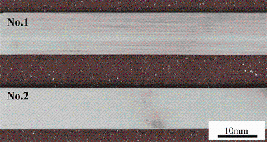
The final annealed sheets were tensile tested by 15% strain along the rolling direction to evaluate the surface ridging behavior. Figure 1 shows the macro-morphologies of the tensile specimens. The specimen of No. 1 shows the corrugations on the surface after tension. Obviously, the specimen of No. 2 shows better surface quality after tension, indicating that this specimen indicates higher resistance against surface ridging. The average roughness (\(R_{\text{a}}\)) and maximum peak (\(R_{\text{p}}\)) were measured and are listed in Table 3. In comparison with the specimen of No. 1, the \(R_{\text{a}}\) and \(R_{\text{p}}\) for the specimen of No. 2 are decreased by 31% and 29%, respectively. This indicates that the hot rolling technology has a big influence on the surface ridging behavior of the final sheets, and decreasing FET properly can enhance the surface ridging resistance of the final sheets.
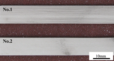 | Fig. 1 Surface morphologies of the final sheets after tensile test by a strain of 15% |
| Table 3 Surface ridging data detected after tensile straining by 15% |
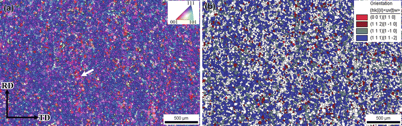
Since the occurrence of the surface ridging of FSS is proposed to relate with the distribution of micro-texture, the micro-texture evolution during manufacture process was monitored. Figure 2 shows the orientation maps of the hot rolled and annealed sheets of the two specimens in longitudinal sections. After hot rolling and annealing, the specimens are mainly composed of equiaxed recrystallized grains. The grains in the surface layer are much finer than those in the center layer, which is caused by the shear deformation on the surface during hot rolling. For the specimen of No. 1, there still exist a few of elongated unrecrystallized grains with {001}//RD orientation (in red color) as indicated by the arrows in Fig. 2a. Besides, some abnormal growth grains are observed at subsurface layer. For the specimen of No. 2, however, the grains are recrystallized completely. There are more fraction of {111}//ND orientations (in blue color) in the center layer. And the grain size in the specimen of No. 2 is much finer than that in the specimen of No. 1.
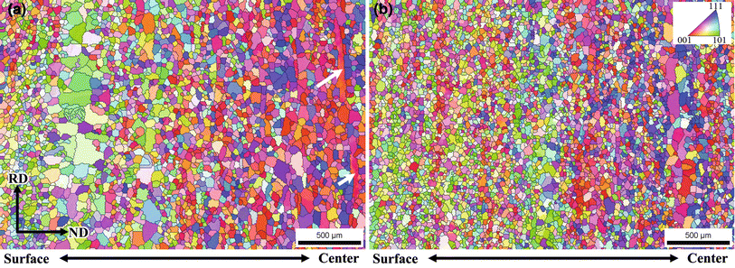 | Fig. 2 Orientation maps of the hot rolled and annealed sheets: a No. 1, b No. 2 |
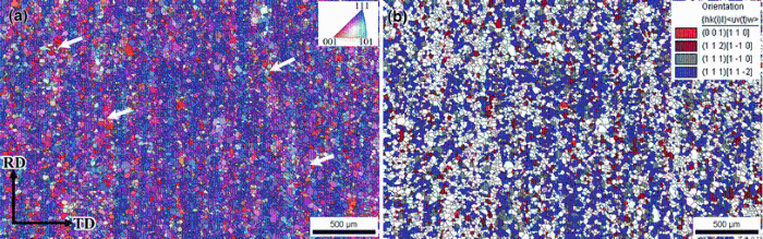
Figure 3 shows the orientation maps and the distributions of specific orientations of the cold rolled and annealed sheet at the center layer of No. 1. To investigate the distribution of micro-texture, a large-scale area (3 mm × 2 mm) was analyzed by EBSD with a step of 5 μ m. From the orientation map, it can be seen that the grain colonies in which the grains with similar orientations get together formed and distributed along the rolling direction (as indicated by arrows in Fig. 3a). The orientation analysis indicates that the grain colonies have mainly orientation with certain deviation from the {001}//RD-α fiber textures. Also, the recrystallization texture with {111} < 112 > and {111} < 110 > orientations tends to be arranged along the rolling direction (Fig. 3b).
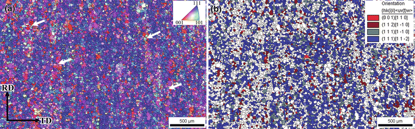 | Fig. 3 Micro-texture of the cold rolled and annealed sheets at center layer of No. 1 specimen: a orientation map, b distribution of specific orientations |
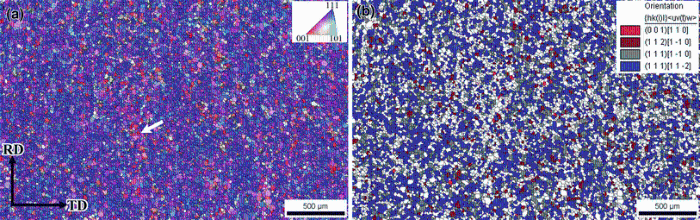
Figure 4 shows the orientation map and the distribution of specific orientations of the cold rolled and annealed sheet at the center layer of No. 2. It can be seen that much more {111}//ND-γ fiber textures including {111} < 112 > and {111} < 110 > orientations are achieved for the specimen of No. 2. And these orientations seem to be distributed homogeneously in the center layer. Although some grain colonies can be observed in the sample as indicated by arrows, the distribution of the grain colonies in the specimens of No. 2 reduced markedly as compared to the specimen of No. 1.
 | Fig. 4 Micro-texture of the cold rolled and annealed sheets at center layer of No. 2 specimen: a orientation map, b distribution of specific orientations |
In this work, two FETs during hot rolling were adopted during the production of FSS sheets. It is found that decreasing the FET can be beneficial for improving the surface quality of the final sheets after tension. Micro-texture analysis indicates that the formation of the grain colonies in the final sheets was markedly reduced for the specimen of No. 2 with relative lower FET.
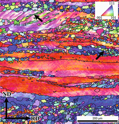
Figure 5 shows the orientation maps for the sheets of No. 2 after hot rolling and partially annealing at 950 ° C for 90 s. Two types of recrystallization nucleation sites can be observed, high-angle grain boundaries and highly misoriented regions within shear bands. Besides, the hot rolled shear bands occurred preferentially in the {111}//ND-oriented grains, and most of the recrystallized grains preserved {111} < 110 > and {111} < 112 > orientations. Doherty et al. [21] have pointed out that the shear bands are resulted from highly localized deformation and preserve high stored energies. The micro-texture analysis in this work indicates that these areas can serve as nuclei sites for recrystallization. However, no in-grain shear bands were observed for the specimen of No. 1 with higher FET.
 | Fig. 5 Orientation maps for the sheets of No. 2 after hot rolling and partial annealing at 950 ° C for 90 s |
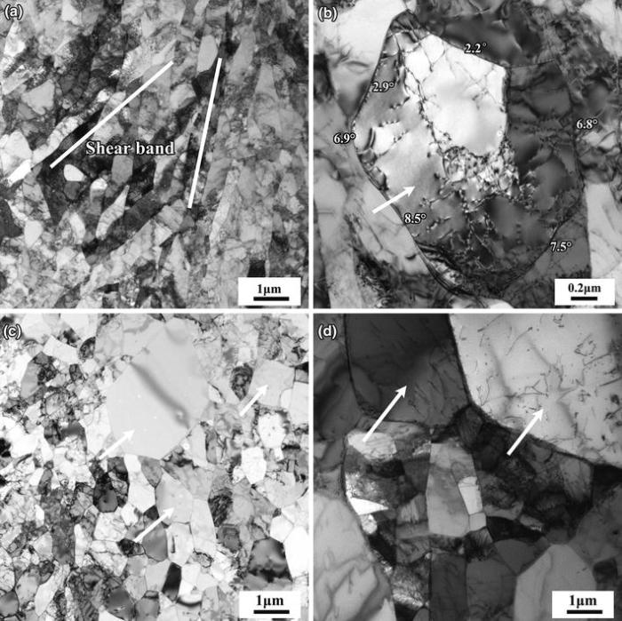
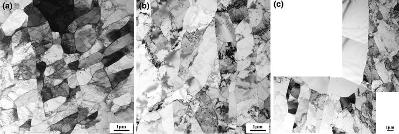
To investigate the recrystallization nucleation mechanisms, the hot rolled slab of No. 2 was annealed at 950 ° C for different time to observe the recrystallization nucleation process by TEM as shown in Fig. 6. After annealing at 950 ° C for 10 s, the deformed grains have little changes, and the in-grain shear bands can be still observed in the grains. This is in the recovery stage (Fig. 6a). As the annealing time increased, the dislocations rearranged through sliding and climbing, and a more equiaxed subgrain structure in the deformed bands formed (as indicated by arrows in Fig. 6b). Moreover, the misorientation angles between the subgrains were calculated through the Kikuchi lines obtained by TEM. The misorientations at the subgrain boundaries were higher than those within the deformation bands. For the larger diameter and high orientation gradient from adjacent matrix [21], the subgrain served as a nucleus for recrystallization and grown into large grain at expense of neighbors (Fig. 6c, d). It is concluded that the formation of recrystallized grains near the in-grain shear bands is to be the coalescence of subgrains.
 | Fig. 6 TEM images showing crystallization in the hot rolled sample (No. 2) annealed at 950 ° C for different time: a 10 s, b 60 s, c 75 s, d 90 s |
Figure 7 shows the TEM images of the hot rolled specimen of No. 1 annealed at 950 ° C for different time. Only nucleation at the grain boundaries can be observed. Since the high recovery rate preserved in the specimen with higher FET, the dislocation density in deformed grains in No. 1 seems to be lower than that in No. 2 (Fig. 7a). With the annealing time increasing, some dislocations rearrange. But no recrystallized nucleation in grain interiors is observed for the specimen annealed for 60 s (Fig. 7b). With increasing annealing time to 105 s, big recrystallization grains nucleate at the grain boundaries (Fig. 7c). That is, for the 21%Cr FSS, when it is hot rolled at relatively higher temperatures, nucleation at the grain boundaries is the main recrystallization mechanism during hot rolling and annealing.
 | Fig. 7 TEM images showing crystallization in the hot rolled sample (No. 1) annealed at 950 ° C for different time: a 30 s, b 60 s, c 105 s |
Tsuji et al. [22, 23, 24] have investigated the effect of initial orientation of solidified columnar crystals on the cold rolling behavior and recrystallization behavior of a 19%Cr FSS. Their works suggested that the formation of the grain colonies is supposed to come from the columnar grains in cast slab. For the high stacking fault energy (SFE) preserved in FSSs [25], dynamic recovery is the main softening behavior during hot rolling and no dynamic recrystallization occurs for the tested material, and also the occurrence of phase transformation between austenite and ferrite [20]. The columnar grains tend to transfer to the {001} < 110 > and {112} < 110 > orientations during hot rolling [26]. These grains show a lower recrystallization rate than other grains during annealing after hot rolling (Fig. 2a). And these grains also tend to be stable during cold rolling and finally evolve to the grain colonies during the final annealing process.
For the specimen of No. 1, with relative higher FET, there are no shear bands that were observed in the hot deformed grains. This is because FSS possesses high SFE, and the dislocation can cross-slip and climb easily at high temperatures, resulting in a high dynamic recovery rate. This high dynamic recovery rate avoids the occurrence of heavy plastic deformation in localization. When the temperature decreases, the dynamic recovery rate becomes slow. The slow rate of dynamic recovery and high deformation resistance at low FET would cause more deformation energy to be preserved in the sample, causing more slip systems to be activated and therefore increasing the formation possibility of shear bands.
The formation of nucleation sites in shear bands would refine the microstructure of the hot rolled and annealed sheet. This is useful to break up the columnar grains. As a result, the formation of grain colonies in the final sheets is reduced by decreasing the FET, resulting in improving the surface ridging resistance of FSS. Therefore, it is recommended that the surface ridging resistance of 21%Cr ultra-purified FSS can be improved by optimizing the hot rolling conditions.
The effects of the FETs on the surface ridging behavior for an ultra-purified 21%Cr ferritic stainless steel have been investigated. The micro-texture analysis reveals that decreasing the FET is beneficial for weakening the formation of grain colonies. This is attributed to the formation of in-grain shear band in the hot rolled specimen with low FET, supplying recrystallization nucleation sites through coalescence of subgrains during subsequent annealing process. The surface ridging of FSS is closed related to the grain colonies. Due to the weakness of grain colony distribution in final sheets by decreasing FET, the surface ridging resistance is improved. It is recommended that to enhance the surface ridging resistance of the 21%Cr ultra-purified FSS, the micro-texture in the final sheet can be optimized by adjusting the hot rolling condition.
This work was supported by the Fundamental Research Funds for the Central Universities of China, the Scientific Research Fund of Liaoning Provincial Education Department under Grant No. L2015120, and the Open Research Fund from the State Key Laboratory of Rolling and Automation, Northeastern University, China (Grant No. 2015003). Part of this work was presented at the International Deep Drawing Research Group Conference (2015).
The authors have declared that no competing interests exist.
| [1] |
|
| [2] |
|
| [3] |
|
| [4] |
|
| [5] |
|
| [6] |
|
| [7] |
|
| [8] |
|
| [9] |
|
| [10] |
|
| [11] |
|
| [12] |
|
| [13] |
|
| [14] |
|
| [15] |
|
| [16] |
|
| [17] |
|
| [18] |
|
| [19] |
|
| [20] |
|
| [21] |
|
| [22] |
|
| [23] |
|
| [24] |
|
| [25] |
|
| [26] |
|