


Influence of Extrusion Joint on Microstructural Evolution and Properties of Mg Alloy Sheet
[Qing-Shan Yang1, 2  , Zu-Jian Yu
1 , Hu-Cheng Pan3 , Qing-Wei Dai1 , Jian-Hui Li1 ]
, Zu-Jian Yu|
|


The mechanical behaviour of AZ31 magnesium alloy sheet with the extrusion joint (EJ) was evaluated. Extruded joint of AZ31 alloy sheets was obtained by the hot extrusion process. Tensile tests were carried out along the extrusion direction at room temperature, and both the non-uniform plastic deformation and the fracture behaviour were studied. It is found that the samples with EJ present significantly deteriorated mechanical properties compared with the EJ-free counterpart. Inhomogeneous microstructure distribution around EJ zone brings in the uncoordinated deformation due to the high density of \(\{ 10\bar{1}2\}\) twins which were readily activated during plastic deformation.
Magnesium (Mg) alloys are evaluated for their use in the applications of automotive, aerospace and electronics [1, 2, 3, 4, 5]. It is well known that wrought Mg alloy has much better combined mechanical properties than their casting counterparts and thus considered as the primary candidates in industry [6, 7, 8, 9, 10]. A large amount of Mg alloy products, especially the semi-finished productions of strips and sheets, are expected to be fabricated as structural components in expanded scale. However, the Mg alloys suffer from poor room temperature formability due to the hexagonal close-packed (h.c.p.) crystallographic structure [11, 12, 13, 14].
Wrought Mg alloys usually exhibit the strong basal texture during thermo-mechanical processing of extrusion and rolling[15, 16, 17]. As a three-dimensional stress process, extrusion can avoid the unexpected problems of cracking and thus has great potential in enhancing formability of Mg alloy sheets [18, 19]. A large amount of works have been conducted on the microstructure evolution and mechanical behaviour of extruded Mg alloy sheets, while much less attention has been paid to establish a qualitative or quantitative correlation between the primary sheet and the following sheet (connected with extruded joint zone) during the extrusion process [20, 21]. The microstructure feature and mechanical behaviour at the joint zone are closely related to the workability. Thus, the comprehensive understanding of this behaviour for Mg alloy sheets should be considered in order to optimize the parameters for enhancing the formability in the following deformation process.
In this work, microstructure of the extruded joint (EJ) and the corresponding mechanical response were performed on the AZ31 alloy sheet with addition of cerium under uniaxial tension. The EJ sample presents a more complex mechanical behaviour because of the inhomogeneous microstructure. The possible deformation mechanisms during tensile tests are also discussed.
The as-received AZ31 alloy sheets (Mg-3.32 Al-0.94 Zn-0.3 Mn-0.71 Ce, wt%) with 500 mm in width and 3 mm in thickness were used in this study. The microstructures were examined by optical microscopy (OM). The (0002) pole figure of AZ31 alloy sheet was measured using an X-ray diffractometer (XRD, Rigaku D/Max 2500) with CuK a radiation. Fracture morphologies were observed by scanning electron microscopy (SEM) and electron backscattered diffraction (EBSD). The specimen was prepared for electron backscatter diffraction by electropolishing at 20 V for 150 s in the AC2 solution at -10 ° C. EBSD data were acquired using HKL Chanel 5 System-equipped FEI Nova 400 FEG-SEM.
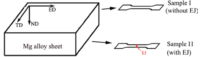
Schematic diagram of the samples for the tensile tests is shown in Fig. 1. Here, the sample I and II were machined from the zones I and II (EJ), respectively. The sample containing the extruded joint was machined from the zone II, as shown in Fig. 1. Dog-bone tensile samples with and without the EJ have a gauge size of 32 mm × 6 mm × 3 mm. Tensile tests were performed at an initial strain rate of 10-3 s-1 using a CMT6305-300KN universal testing machine along the extrusion direction at room temperature.
 | Fig. 1 Schematic diagram of the samples for the tensile tests |
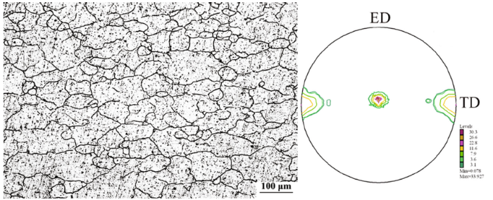
Figure 2 demonstrates the optical microscopic image and (0002) pole figure of the as-received AZ31 alloy sheets along ND-ED plane. The microstructure is inhomogeneous, and a few fine dynamically recrystallized (DRX) grains with the size of about 50 μ m are observed. The fine DRXed grains are embedded in elongated grains with the size of ~200 μ m, which manifests that the dynamical recrystallization is not fully finished during the hot extrusion process [22]. As shown in Fig. 2, the (0002) pole figure of AZ31 alloy sheet possesses a strong basal texture with some c-axis orientations of basal planes rotated to be near TD (c-axis//TD texture).
 | Fig. 2 Optical microstructure and (0002) pole figure of AZ31 alloy sheet |
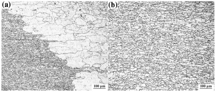
Figure 3 illustrates the microstructure of the EJ sample (ED-ND plane) in the joint zone. An apparent abnormal grain growth can be observed under the present extrusion conditions. It seems that the grains of the sheet exhibit a distinct boundary with convex shape between the two sheets. To demonstrate the microstructure clearly, optical micrographs of the extrusion joint zone at top (TEJ) and middle layer (MEJ) are presented in Fig. 4. The joint zone is composed of long strip grains of about 20 μ m in size surrounded by coarse grains of about 300 μ m. The microstructure indicates the nuclei of MEJ zone are not developed to DRXed grains. The thermal activity of MEJ zone was not high enough to stimulate the small grains continuously growing up, and the sheets are not prone to be DRXed during the extrusion process[23, 24].
 | Fig. 3 Optical microstructure of the extrusion joint (EJ) sample at the joint zone |
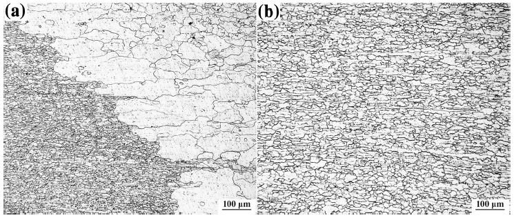 | Fig. 4 Optical microstructures of the joint zone at top a and middle b layers |
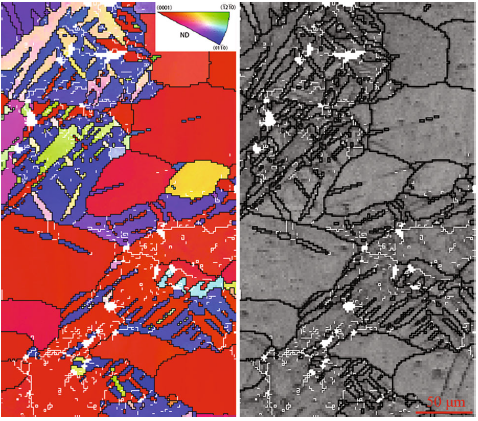
Figure 5 describes EBSD results of the microstructure and the misorientation distribution for AZ31 alloy sheet at the middle layer of the EJ zone. In the inverse pole figure (IPF) map, the grain boundaries were displayed by various lines lying on the misorientation angles of the grain-to-grain boundaries: white for 2° < θ < 15° (low-angle boundaries, LABs) and black for 15° < θ < 90° (high-angle boundaries, HABs) [25]. It is observed that the microstructure of MEJ zone mainly included a higher density of low-angle misorientations, as is seen in the misorientation distribution of AZ31 alloy sheet in Fig. 5. In general, a higher density of high-angle misorientations suggests more random distribution of the grain orientations. The recrystallization and nucleation of new grains in the sheets were different from those of the parent grains at orientation angles. The recrystallization mechanism could be considered as the rotational dynamic recrystallization, which was attributed to more new recrystallized grains with HABs. The high volume fraction of the dynamic recrystallization primarily rooted in the factor of the action between the dislocation and the high extrusion temperature. Thus, a higher density of low-angle misorientations suggests that the sheets of MEJ zone exhibit un-DRXed grains. In addition, the microstructure at MEJ shows a basal texture.
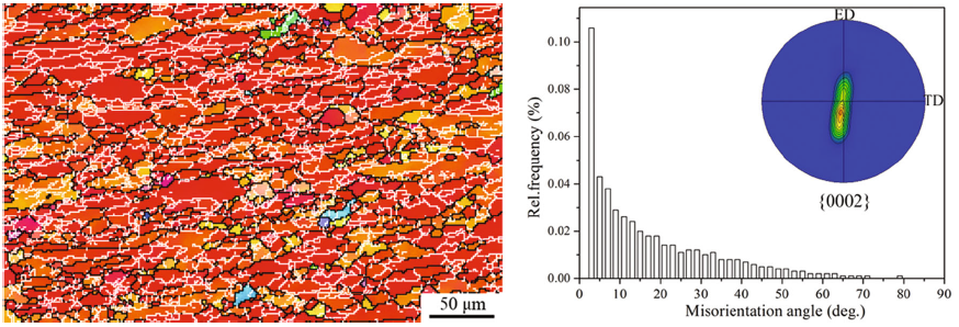 | Fig. 5 EBSD results of the microstructure and the misorientation distribution for AZ31 alloy sheet |
Figure 6 depicts true stress-strain curves corresponding tensile tests along ED for the sample I (without EJ) and II (with EJ) at room temperature. Mechanical properties of yield strength (YS, 0.2% offset strength), the ultimate tensile strength (UTS) and the fracture elongation (FE) for sample I and II are listed in Table 1. It is obvious that the fracture elongation of EJ sample was reduced by approximately 50%. Compared with the strength of normal samples, that of EJ samples changes slightly, YS increases from 184 to 197 MPa, while the UTS decreases from 268 to 252 MPa, respectively. Mechanical properties of AZ31 sheets have been notably deteriorated by the presence of the extruded joint.
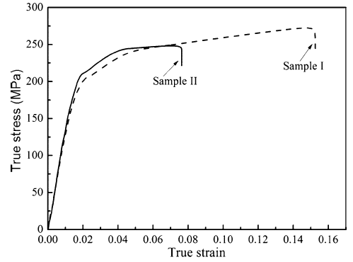 | Fig. 6 True stress-strain response of AZ31 alloy sheets |
| Table 1 Tensile properties of the AZ31 alloy sheet |
The work-hardening rate (WH, θ ) versus net flow stress (σ - σ 0.2) curves of the sample I and II is displayed in Fig. 7. The WH of both samples was evaluated by means of the macroscopic WH rate: θ = dσ /dε , where σ and ε are the true stress and true strain, respectively [26, 27]. The yield stress σ 0.2 was subtracted from σ . The (σ - σ 0.2) expresses the dislocation contribution to the flow stress during deformation. It can be seen that the sample II exhibits a steep hardening decrease in the initial period (Stage I) of the work-hardening rate versus flow stress curves because of a short elastoplastic transition. Meanwhile, it also exhibits a faster slope at stage II of \({\text{WH}}\left( {\theta_{\text{II}}^{\text{II}} } \right)\) and the value of the slope at stage II was smaller compared with the one in sample I. The difference in the slope of stage II is probably related to the different dislocation densities stored in these two deformed samples. It is considered that the sample II possesses a relatively higher density of dislocations owing to the extruded joint and thus leads to a steeper slope of stage II. It should be considered that deformation twinning can produce an extrahardening effect acting as obstacles to the dislocation slip[28, 29]. Twin boundaries act as the barriers for dislocation slips and become a source of work hardening. In addition, it can be observed that the slope during stage III is almost parallel irrespective of the grain size because of the dynamic recovery.
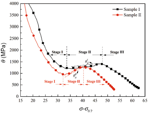 | Fig. 7 Work-hardening (WH, θ ) behaviour of the sample I and II |
To understand the microstructure evolution during tension along ED better, optical micrographs of the fractured tensile sample (FTS) are shown in Fig. 8. The fracture locations of both types of the samples were significantly different. Most of twins are around the fracture surface in the FTS I, as shown in Fig. 8a, b. For FTS II, it reveals that enough twins exist around the fracture at EJ zone. Meanwhile, structure of the EJ area is still remained after the fracture, as shown in Fig. 8c. It can be seen that the volume fraction of twins near the fracture surface of FTS II is higher than that in FTS I. There are significant differences in the grain size and extension twins among the different samples, causing deformation incompatibility and therefore generating stress concentrations and then accelerating the fracture along the EJ region. For the sample II, twinning may be the main mechanism plastic deformation rather than slips favoured orientation grains are gradually exhausted.
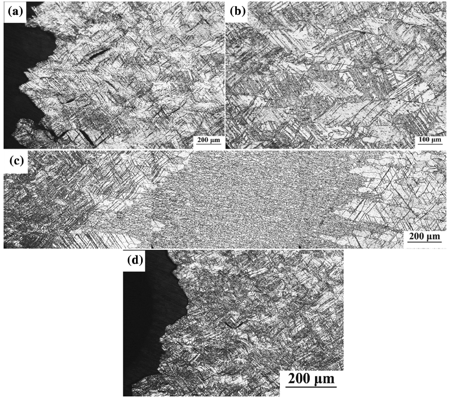 | Fig. 8 Optical micrographs of fractured tensile samples: near the fracture surface a and away from the fracture surface b of the sample I; the joint zone c and near the fracture surface d of sample II |
EBSD results show that fractured tensile samples consist of large number of \(\{ 10\bar{1}2\}\) extension twin boundaries, as shown in Fig. 9. It has been reported that yielding in tension deformation along ED is dominated by prismatic slip and extension twin for the extruded Mg alloy sheets with a strong basal texture[19, 30]. Since the as-received sheets show a strong basal texture associated with some c-axis orientations rotating to TD, it confirms that the formation of the c-axis//TD texture is attributed to the extension twin[31]. In general, twinning plays an important role in the plastic deformation of Mg alloys at room temperature [32, 33]. These twins are generated during tension in response to the local stress states, which is ascribed to the deformation of neighbouring grains. It is well known that the basal slip along \({< }11\bar{2}0{> }\) (< a> ) direction, two non-basal slip (\(\{10\bar{1}0\}\)— prismatic slips and \(\{ 10\overline{1} 1\}\)— pyramidal slip) and twinning are the active deformation modes of Mg alloys. The critical resolved shear stress (CRSS) assesses the ability of plastic deformation in Mg alloys. In general, it can be considered that CRSSbasal < CRSStwinning < CRSSprismatic < CRSSpyramidal[34, 35]. For the sheets with the c-axis//TD texture, basal slips dominate at the beginning of deformation. And then the non-basal slips are activated to accommodate the deformation as the stress reaches an enough high level [36]. For the sample I, basal slip can be easily activated, and the tensile failure often exhibits an obvious shearing feature. For sample II, the characteristic of the extruded joint is the uncoordinated deformation. It is found that strong inhomogeneous plastic deformation occurs in the EJ side due to the fact that the grains are favourably oriented for extension twins. Thus, the high \(\{ 10\bar{1}2\}\) twin activity plays an important role at the initiation of deformation.
 | Fig. 9 EBSD maps of the fractured tensile samples |
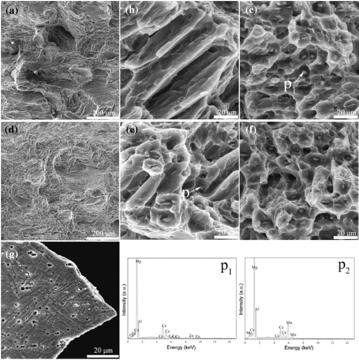
After tension to failure, the different fracture modes of two samples should be linked with the difference in the fracture elongation. Figure 10 shows morphologies of the tensile fracture surface and EDS results of these two samples. Here, Fig. 10b, c is partial enlargement of Fig. 10a (Sample I), and Fig. 10e, f is partial enlargement of Fig. 10d (Sample II). Figure 10g shows the morphology near the fracture surface of sample II. It can be clearly seen that both FTS I and FTS II are characterized by a good deal of plastic dimples and cracked particles[37, 38]. However, the fracture of sample I shares more features with the quasicleavage, as seen in Fig. 10a, d. As mentioned above, the FE of sample I is larger than the one in sample II, which is attributed to the appearance of finer equiaxed grains in the EJ zone, resulting in the uncoordinated deformation during the tensile tests. Consequently, less plastic strain and necking are generated in tensile fracture surfaces of sample II.
 | Fig. 10 Tensile fracture morphologies of the sample I (a, b, c) and sample II (d, e, f). (g) Near the fracture surface morphology of sample II. Energy dispersive spectroscopy (EDS) analysis of points (p1 and p2) |
AZ31 sheets with extrusion joint zone were employed to evaluate the mechanical properties and fracture behaviour during tensile testing. The room temperature ductility of the sample with EJ was reduced by ~50% compared with those of the normal sheets without EJ. The grains in the side of the fracture locations are favourably oriented for extension twinning for EJ samples, decreasing the ductility of the sample during tensile tests. This is attributed to the uncoordinated deformation due to the extremely inhomogeneous microstructure in the EJ zone. The uncoordinated deformation made grain orientations rotate into hard orientations resulting from the deformation twinning.
The authors are grateful for the financial supports from China Postdoctoral Science Foundation (Nos. 2015M572451, 2015M581350), Chongqing Postdoctoral Research Special Foundation (No. Xm2015015), Chongqing Science and Technology Commission (No. cstc2014fazktjcsf50004), National Natural Science Foundation of China (No. 51501025).
The authors have declared that no competing interests exist.
| [1] |
|
| [2] |
|
| [3] |
|
| [4] |
|
| [5] |
|
| [6] |
|
| [7] |
|
| [8] |
|
| [9] |
|
| [10] |
|
| [11] |
|
| [12] |
|
| [13] |
|
| [14] |
|
| [15] |
|
| [16] |
|
| [17] |
|
| [18] |
|
| [19] |
|
| [20] |
|
| [21] |
|
| [22] |
|
| [23] |
|
| [24] |
|
| [25] |
|
| [26] |
|
| [27] |
|
| [28] |
|
| [29] |
|
| [30] |
|
| [31] |
|
| [32] |
|
| [33] |
|
| [34] |
|
| [35] |
|
| [36] |
|
| [37] |
|
| [38] |
|