


Arc Erosion Behavior of Cu-0.23Be-0.84Co Alloy after Heat Treatment: An Experimental Study
[Yanjun Zhou1 , Kexing Song2, 3  , Jiandong Xing
1 , Zhou Li4 , Xiuhua Guo2, 3 ]
, Jiandong Xing|
|


The arc erosion behavior of Cu-0.23Be-0.84Co alloy after heat treatment was investigated experimentally by a JF04C electric contact test system. The arc duration, arc energy, contact resistance and contact pressure of Cu-0.23Be-0.84Co alloy after solution treatment and aging treatment were analyzed. The arc erosion morphologies were contrastively observed by a three-dimensional measuring system and scanning electron microscopy. For the Cu-0.23Be-0.84Co alloy in solution state and aging state, the maximum values of arc duration are 90 and 110 ms, and the arc energies are 15,000 and 18,000 mJ, respectively. The maximum value of the contact resistance of Cu-0.23Be-0.84Co alloy in different states is about 33 mΩ. The contact pressure of Cu-0.23Be-0.84Co alloy in solution state generally changes between 50 and 60 cN during whole make-and-break contacts, while in aging state, it has a larger fluctuation range. Moreover, the quality of moving contact (anode) decreases, while static contact (cathode) increases. The materials transfer from anode to cathode during make-and-break contacts. The total mass losses of Cu-0.23Be-0.84Co alloy in solution state and aging state are 3 and 1.2 mg, respectively. In addition, a number of discrete corrosion pits, molten droplet, porosity and cavity distribute on the surface of moving contact and static contact. The arc erosion model of Cu-0.23Be-0.84Co alloy in make-and-break contact was built. The arc erosion resistance of Cu-0.23Be-0.84Co alloy after heat treatment is closely related to the microstructure and the properties of contact materials. This experimental study is important to evaluate the anode or cathode electrocorrosion fatigue life.
Electrical connectors are widely used in the key parts of aerospace, electronic communications and military industry. The contact elements of pin and socket are conductive parts and core components of electric connectors [1, 2, 3]. The electrical contact materials should have excellent combination properties of electrical, thermal, mechanical and wear resistance to perform their function reliability [4, 5, 6, 7]. The electric strength test of connector pin (male contact) and socket (female contact) should be carried out to study the contact material performance of flashover resistance (surface discharge) and sparks discharge (air discharge) or breakdown (disruptive discharge) [8, 9]. Cu-Be alloys are the preferred materials in critical electrical components because of its excellent mechanical properties, conductivity and erosion resistance [10, 11]. As the typical precipitation strengthening alloys, the formability of Cu-Be alloys can be raised by solution treatment, and its strength and hardness are improved significantly by the subsequent aging treatment. Cu-Be alloys usually consist of (0.2-2.0) wt% Be and a small amount of cobalt or nickel. The beryllium obviously affects the properties of Cu-Be alloys. For instance, with the increase in beryllium content, the strength increases, while the electrical and thermal conductivity decrease. Cu-Be alloys can be divided into two types of the high strength ((1.8-2.0) wt% Be) and the high conductivity ((0.2-0.6) wt% Be) [10]. High-strength Cu-Be alloys are suitable for the structural parts of high-speed connectors, while high-conductivity Cu-Be alloys are available for the fixed contact of connectors assembly with high electric contact performance requirements.
Sudhakar et al. [7] investigated the influence of cutting temperature on the machinability, mechanical properties, microstructure and fracture morphology of Cu-2Be alloy. Gallo et al. [12] summarized the results from uniaxial-tension stress-controlled fatigue tests performed at different temperatures up to 650 ° C on Cu-Be alloy. Yagmur [13] presented the effect of the microstructure on internal friction and Young’ s modulus, and the influence of transformed phases caused by precipitation hardening on these properties of an aged Cu-Be alloy. Xie et al. [14] investigated the precipitation behavior and strengthening of a Cu-2.0 wt% Be alloy and found that the electrical conductivity increases by the precipitation of solute elements from copper matrix. The change in electric conductivity can be used to describe the dynamic process of precipitation by an equation based on the Avrami law. Rosenthal [15] examined the fracture of Cu-Be alloy in various loading modes and analyzed the fracture mechanism. For the tensile mode, the dominant fracture mode is defined as a dimpled intergranular in Cu-Be alloy. Tang et al. [16] investigated the effects of normal aging (NA) and interrupted aging (IA) on the mechanical properties of a Cu-Be-Co-Ni alloy by tensile and Kahn tear tests. It is confirmed that IA process could significantly improve the uniform elongation and plane stress fracture toughness with tiny decrease in ultimate tensile strength. Monzen et al. [17] presented that the additions of 0.01 and 0.03 wt% Mg can enhance the bend formability and strength of Cu-1.8Be-0.21Co alloy aged at 320 ° C for 30 min. Pang et al. [18] studied the fatigue strength of Cu-Be alloy during tensile testing. It is indicated that the optimum fatigue strength of the Cu-Be alloy at 107 cycles is 323 MPa, and the improvement in the tensile strength cannot always achieve the optimum fatigue strength. Behjati et al. [19] explored the influence of aging process on sound velocity of C17200 Cu-Be alloy. Satoshi et al. [20] and Li et al. [21] investigated the mechanical, electrical properties and microstructure, and the precipitation process and its effects on properties of aged Cu-Ni-Be alloys. Woodcraft et al. [22] and Karaki et al. [23] investigated the thermal conductivity of Cu-Be alloy below 1 K, and they suggested that the thermal conduction is predominately electronic. Rebelo et al. [24] provided a thermal erosion model of high-strength Cu-Be alloy to be as a justification for achievement of distinct surface integrity using materials with different thermal properties. The tribological behavior of two Cu-Be alloys was investigated under dry sliding conditions against an AISI M2 steel counterface, as referred by Straffelini et al. [25]. Argibay et al. [26] stated that the friction coefficients of C17200 alloy varied from 0.30 at 2.5m/s to 0.15 at 7.5 m/s and fatigue dominated wear of the Cu-Be fiber tips. Nikam and Reddy [27] studied the properties of copper-beryllium alloy in simulated fuel cell environment. Hu et al. [28] reported that the effect of the magnetic field on corrosion process of Cu-Be alloys in NaCl solution. The magnetic field can accelerate the diffusion of CuCl2- from the electrode surface and delay the formation of Cu2O. Most of above investigations have focused on the mechanical properties (tensile/yield strength, bending strength, fatigue strength, etc.), electrical properties, thermal properties, tribological properties and corrosion properties of high-strength Cu-Be alloys. However, the arc erosion behavior of Cu-Be alloys used in electrical connector has not been clarified yet. Especially for the high-conductivity Cu-Be-Co alloys, there are no reports about the property of arc erosion resistance during electrical contact process.
Therefore, the objective of this study is to focus on the arc erosion behavior of Cu-0.23Be-0.84Co alloy. The characteristic parameters of arc discharge such as arc duration, arc energy, contact resistance and contact pressure of Cu-0.23Be-0.84Co alloy in solution state and aging state were systematically analyzed. The arc erosion morphologies were contrastively observed by a three-dimensional measuring system and scanning electron microscopy (SEM). The arc erosion model of Cu-0.23Be-0.84Co alloy in make-and-break contact was proposed.
The ingot with a nominal composition of Cu-0.2Be-0.8Co was prepared by using a KGPT200-2.5 medium frequency induction furnace. The raw materials were cathode copper (99.99 wt%), Cu-3.3 wt% Be master alloy and Co flake (99.95 wt%). The melting temperature was between 1150 and 1250 ° C and the P-Cu alloy was used for deoxidization. An ingot with a diameter of 100 mm was obtained by pouring molten metals into a metallic mold of cast iron. The alloy consisted of 0.23 wt% Be and 0.84 wt% Co along with balance of copper after chemical analysis. Then, the ingot was forged by a C41-250 air forging hammer and subsequently extruded by an XJ-500 horizontal extruder. The temperature of hot-forge and thermal extrusion was between 850 and 880 ° C. The diameter changed from 100 mm of as-cast to 20 mm of as-extruded. Next, the extrusion specimens were cold drawing up to 36% reduction in area, and the diameter reduced from 20 to 16 mm. Furthermore, the specimens with a diameter of 16 mm and a length of 10 mm were cut from the bar. The specimens were solution treated at 950 ° C for 1 h and then quenched in water, followed by aging at 480 ° C holding for 4 h and cooled in air. The solution and aging treatment is a function of temperature and time. According to the phase diagram of Cu-Be alloys [29], and the inner relationship between process parameters of heat treatment (temperature, holding time) and performance and microstructure of Cu-0.23Be-0.84Co alloy, the proper parameters of solution and aging treatment were chosen in this paper. The heat treatment was carried out by a KSS-1200 vacuum tube furnace with an accuracy of about ± 2 ° C.
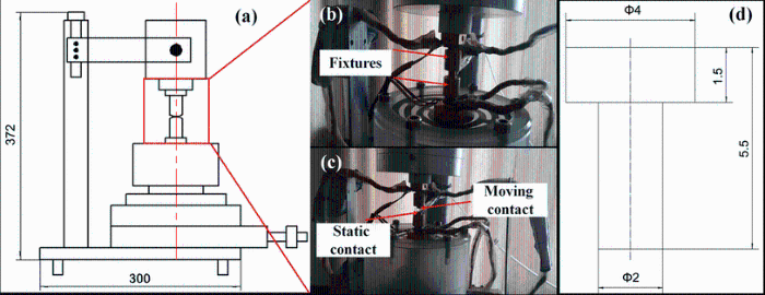
The electrical contact experiment was carried out by a JF04C electric contact test system (see Fig. 1). This test system simulates the actual movement of the contacts by adopting an action device under computer control. A pair of contacts is fixed on the equipment fixture. The moving contact and the static contact are anode and cathode, respectively. The size of the moving contact and the static contact is the same, while the installation direction is opposite (see Fig. 1d). The contact spacing and contact pressure are controlled by adjusting the step/block device. The contact resistance is obtained through constant current source and the corresponding amplifying circuit. The changes in the mechanical parameters are measured by mechanical sensor. Under a certain condition of voltage, current, closure pressure and frequency, the electrical erosion resistance of the contact materials is investigated through simulating the opening and closing process of contact. According to the shape of contacts in Fig. 1d, the prepared Cu-0.23Be-0.84Co alloy in solution condition and aging condition was processed into contact pairs by precision CNC machine tool. The input parameters are given in Table 1. The moving contact and static contact from the contact to disconnect were defined as once test, and the total test number was set as 5000 times.
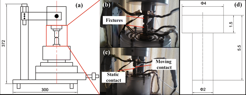 | Fig. 1 JF04C electric contact test system: a schematic diagram of test-bed; b contact pairs in contact status; ccontact pairs in disconnect status; d the shape and dimensions of the contacts |
| Table 1 Input parameters of electrical contact test |
The arc duration, arc energy, contact resistance and contact pressure were recorded periodically by the JF04C electric contact test system. The experimental mass loss of contacts was weighed using a precision balance. The surface morphologies of the moving contact and static contact were observed using the three-dimensional measuring system. The electric erosion morphologies of the contacts were investigated by scanning electron microscopy (SEM; JEOL Model 5610 LV, Tokyo, Japan). Before observation, the erosion surface was dealt with thoroughly using ethanol liquid in a KQ5200 ultrasonic stirrer. The microstructures of Cu-0.23Be-0.84Co alloy in solution condition and aging condition were observed by transmission electron microscopy (TEM; JEOL Model 2100 HUR, Tokyo, Japan) with a LaB6 filament at operating voltages of 200 kV. The images were taken by a Gatan 694 slow scan CCD camera.
Figure 2 shows the changes in arc duration, arc energy, contact resistance and contact pressure as a function of test number of Cu-0.23Be-0.84Co alloy in solution state and aging state, respectively. Figure 2a, b shows that the arc duration in the solution state and the aging state is obviously different. Figure 2a shows that the change in the arc duration in solution state is intermittent. When the test number of make-and-break contacts is below 500 times, the arc duration in solution state ranges from 10 to 20 ms. When the test number ranges from 500 to 1000 times, the arc duration changes remarkably from 20 to 90 ms. With increasing the test number to 1000-2000 times and 2700-4000 times, the arc duration changes at a higher level of 50-90 ms. While the test number is 2000-2500 times or greater than 4000 times, the arc duration in solution state is zero, and there is no arc discharge between moving contact and static contact (see Fig. 2a). However, compared with Fig. 2a, the regular change in arc duration as a function of test number in aging state is shown in Fig. 2b. As a cycle period is 500 times in make-and-break contacts, the arc duration changes alternately from the range of 10-20 ms to 60-110 ms. With increasing test number, arc duration is basically stable at the lower values, while the proportion of longer arc duration decreases. Similarly, the variation trend of arc energy in solution state and aging state is the same as that of the arc duration, as shown in Fig. 2c, d. Figure 2c shows that the arc energy is 2000-3000 mJ when the test number is below 500 times. With increasing the test number from 500 to 1000 times, the fluctuation range of arc energy is 3000-15, 000 mJ. When the test number increases to 1000-2000 times and 2700-4000 times, the arc energy changes at a higher level range of 5000-14, 000 mJ. While the test number is 2000-2500 times or greater than 4000 times, the arc energy is zero. However, the change in the arc energy in aging state is regular as shown in Fig. 2d. The arc energy changes alternately from the range of 1000-2000 to 8000-18, 000 mJ as a cycle period of 500 times. With increasing test number, the arc energy is basically stable at the lower values. The arc duration during make-and-break contact directly affects the arc energy and then affects the temperature rise of the contact surface and the electrical life [30]. For a certain contact system, the main factor affecting the arc duration and the arc energy is the state of the contact surface. With the increase in test number, the contact surface becomes uneven due to arc erosion. The arc duration extends and the arc energy increases. However, why is there no arc energy between 4000 and 5000 times in solution state, but exists in aging state, as shown in Fig. 2a-d? The intermittent of the arc energy and the arc duration in solution alloy is caused by the oscillation of discharge channel and the fluctuation of contact surface in arc discharge area. This phenomenon is closely related to the arc erosion resistant ability of the alloy [31]. During the arc discharge duration, the location and shape of the discharge channel are not fixed. At the beginning of the discharge, the fluctuation of discharge channel is not evident, and the arc erosion is not serious. With the continuous discharge, the fluctuation of discharge is more and more obvious due to transverse vibration, even leading to the disappearance of arc discharge. For the Cu-0.23Be-0.84Co alloy in solution state, after a certain test number, the arc erosion of the surface is serious due to a large number of material transfer, splash and the formation of eroded crater. The structure of discharge channel changes and the arc discharge is not formed during make-and-break contacts. So the arc duration and the arc energy are zero between 4000 and 5000 times in solution state. Nevertheless, the arc erosion of Cu-0.23Be-0.84Co alloy in aging state under the same test numbers is not serious. The discharge channel is completed, and the arc discharge is continuous. This phenomenon means that the arc erosion resistance of Cu-0.23Be-0.84Co alloy in aging state is superior to that of solution state under the same electric contact environment and test number of make-and-break contacts. Especially, when the test number is more than 4000 times, the surface performance of the alloy in solution state already cannot meet the service demands of contacts.
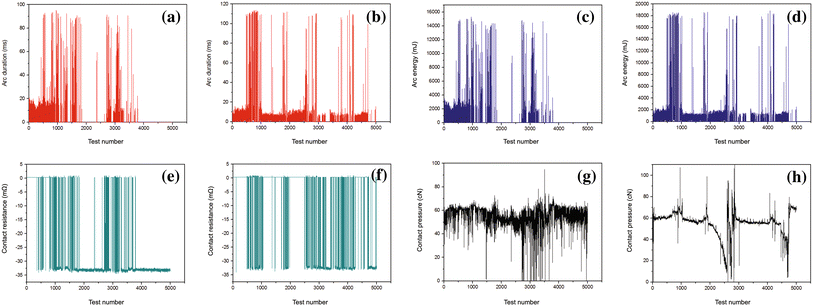 | Fig. 2 Changes in arc duration, arc energy, contact resistance and contact pressure as function of test number of Cu-0.23Be-0.84Co alloy in different states: a arc duration in solution state; b arc duration in aging state; carc energy in solution state; d arc energy in aging state; e contact resistance in solution state; f contact resistance in aging state; g contact pressure in solution state; h contact pressure in aging state |
In addition, Fig. 2e, f shows the changes in contact resistance as a function of the test number of Cu-0.23Be-0.84Co alloy in solution and aging state, respectively. The maximum contact resistance of Cu-0.23Be-0.84Co alloy in different states is 33 mΩ . When the test number is less than 500 times, the contact resistance in solution state is zero. The maximum value of contact resistance appears in 1800-2800 times and 4000-5000 times. However, in the aging state, the contact resistance is zero when the test number is less than 500 times or is 1000-1500 times and 2000-2500 times. The increase in contact resistance is related to the development of surface film on the contact surface [30]. During the make-and-break operation, the arc discharge leads to the surface damage and formation of surface film. With the increase in surface film thickness, the contact resistance increases. Moreover, as shown in Fig. 2g, h, the contact pressure of Cu-0.23Be-0.84Co alloy in solution state generally changes between 50 and 60 cN during whole make-and-break contacts, except for 2700-3700 times. Nevertheless, the contact pressure in aging state has a large fluctuation during make-and-break contacts.
Table 2 shows the quality transfer and total mass losses of contact materials in different states. The quality of moving contact (anode) decreases, while static contact (cathode) increases. The materials transfer from anode to cathode during make-and-break contacts. The arc erosion rate of the moving contact (anode) is higher than that of the static contact (cathode). Moreover, the mass loss of moving contact (anode) is much greater than the mass gain of static contact (cathode). It is concluded that the arc erosion leads to the spatter and even vaporization of moving contact (anode). Generally, the total mass losses of Cu-0.23Be-0.84Co alloy in solution and aging state are 3 mg and 1.2 mg, respectively (see Table 2). During the arc discharge, the contact area is small and the contact resistance is large. A good deal of heat is produced, and Joule effect makes the sharp temperature rise of contact materials. This phenomenon leads to the melting, vaporization, adhesion and spatter of metals, and then results in the transfer and mass loss of materials. In addition, the total mass losses are closely related to the splash of metal droplets, the evaporation of the metal vapors, the transfer of metals between anode (moving contact) and cathode (static contact). Furthermore, compared with the metal ion, the electron has a very light quality and a very fast movement speed. So the energy of electron bombardment anode (moving contact) is much greater than that of the metal ion to cathode (static contact) [32]. Part of anode materials splash into the surrounding environment and the others in molten pool form the metal droplets and deposit on the surface of cathode (static contact). Therefore, the mass losses of anode (moving contact) are greater than those of cathode (static contact) (see Table 2).
| Table 2 Quality transfer and total mass losses of the contact materials in different states |
Figure 3 shows the three-dimensional surface morphologies of moving contact (anode) and static contact (cathode) of Cu-0.23Be-0.84Co alloy in solution and aging state. Figure 3a shows that the whole three-dimensional surface morphology of moving contact (anode) in solution state is accidented. Large concave pits form on the local region of moving contact surface due to materials transfer and spatter. A number of columnar pimplings and pits distribute on the edge of moving contact surface. Figure 3b shows that the three-dimensional surface morphology of the static contact (cathode) in solution state is obviously different with that of moving contact. The whole surface morphology is like as undulating mountain peaks. The upper surface of the peak shape bulges is smooth, which indicates that it formed from the solidification and accumulation of molten metal. Figure 3c and (d) shows the whole three-dimensional surface morphology of moving contact (anode) and static contact (cathode) in aging state. The whole surface morphology of moving contact (anode) is shallow and step type. Many columnar pimplings distribute on the surface and small concave pits form on the local area due to materials transfer and spatter (see Fig. 3c). The little undulations as disturbed water display on the surface of static contact (cathode). Except for columnar pimplings, the pimplings with round-hill shape form on the surface due to the flow, solidification and accumulation of molten metals (see Fig. 3d).
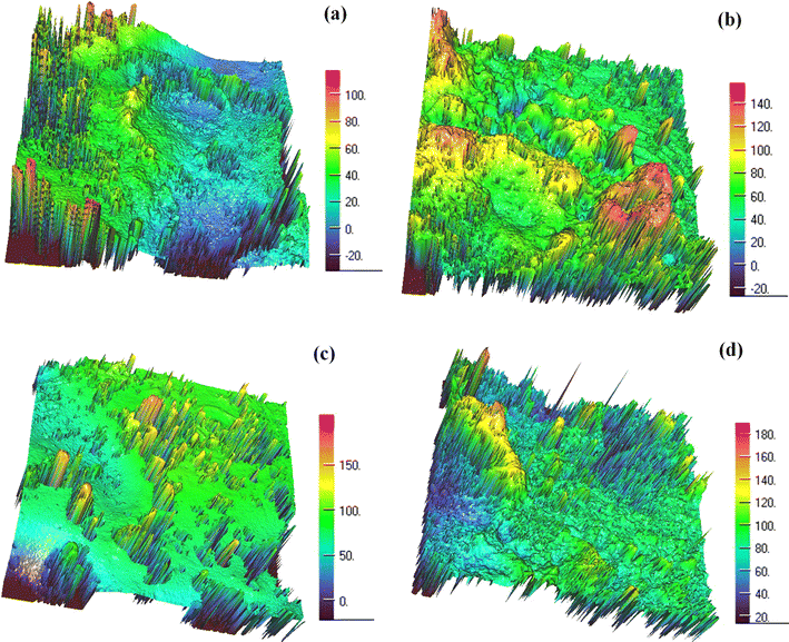 | Fig. 3 Three-dimensional surface morphologies of moving contact (anode) and static contact (cathode) of Cu-0.23Be-0.84Co alloy in different states: a moving contact in solution state; b moving contact in aging state; cstatic contact in solution state; d static contact in aging state |
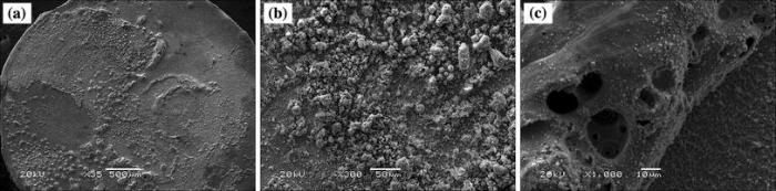
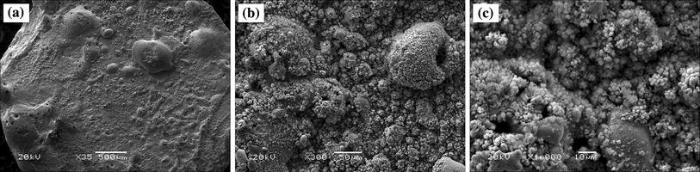
Figure 4 shows the SEM images of moving contact (anode) of Cu-0.23Be-0.84Co alloy in solution state. Figure 4a shows that the surface morphology is accidented. There are large areas of material peeling off and a number of bulges with spherical or irregular shape and different sizes to distribute on the contact surface. These bulges derive from the solidification of molten droplets caused by arc discharge. Furthermore, many holes with large and deep size and few microcracks distribute on the molten droplets, as shown in Fig. 4c. The arc erosion leads to melting and even vaporization of contact surface, and part of gas is absorbed by the molten metals. Then, the molten layer is rapidly cooled in the end of arc discharge. The gas in molten metals is hard to escape and finally leads to the formation of holes. Figure 5 shows the SEM images of static contact of Cu-0.23Be-0.84Co alloy in solution state. Figure 5a shows that the surface morphologies are uneven. There are significant flow layer of molten metals and a large number of molten droplets with different shapes and size to distribute on the contact surface. The quantity and size of holes on static contact are more than those of moving contact (see Fig. 5a). Figure 5b, c shows that the arc erosion morphologies are typical coral structure or flocculent structure. The small holes and molten droplets distribute among the coral structure or flocculent structure, which reveals the occurrence of metal splash in the process of arc discharge. The SEM images of moving contact in aging state are shown in Fig. 6. The surface morphologies are rough with discontinuous peeling off area. A large number of pitting appear on the moving contact surface. The molten droplet bulges with different shape and size distribute on local area (see Fig. 6a). In addition, many large and deep holes with smooth edges are observed on the molten droplets (see Fig. 6b). Furthermore, the molten droplets with petal-shaped distribute uniformly on the contact surface due to the melting and solidification of metals, as shown in Fig. 6c. Figure 7 shows SEM images of static contact of Cu-0.23Be-0.84Co alloy in aging state. Figure 7a shows that the whole surface morphology of static contact is a significant flow layer of liquid metal. The large molten droplets with shallow denudation and deep holes are also observed on contact surface. The electric erosion morphology with coral structure is observed by further amplification. The small holes and molten droplets distribute among the coral structure (see Fig. 7b, c).
 | Fig. 4 SEM images of moving contact of Cu-0.23Be-0.84Co alloy in solution state at different magnifications |
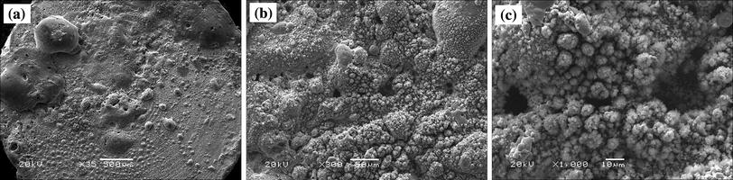 | Fig. 5 SEM images of static contact of Cu-0.23Be-0.84Co alloy in solution state at different magnifications |
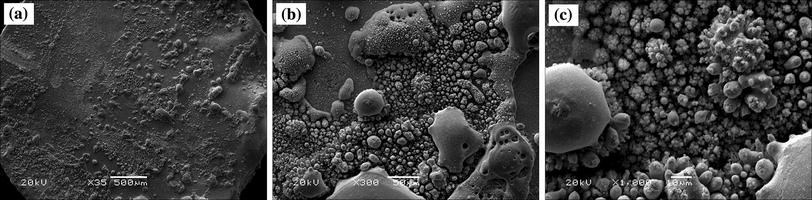 | Fig. 6 SEM images of moving contact of Cu-0.23Be-0.84Co alloy in aging state at different magnifications |
 | Fig. 7 SEM images of static contact of Cu-0.23Be-0.84Co alloy in aging state at different magnifications |
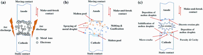
The working conditions between the moving contact and the static contact can be divided into static contact state, dynamic make contact process and dynamic break contact processes [32, 33]. The contact surfaces of moving contact and static contact are uneven under microscale. Under static contact state, the contact mode between anode and cathode is only point contact or line contact. So the cross-sectional area of conductive contact spot is smaller. It will cause the increase in current density and contact resistance when the current flows through actual contact surface. The temperature rise of contact surface derived from Joule heat can result in the plastic deformation of partial conductive contact spot. Furthermore, the molten pool forms on the contact surface and even a partial metals in molten pool splash in the form of small droplets. When the moving contact (anode) and static contact (cathode) are in the process of establishing current flow (i.e., making) or interrupting the row of current (i.e., breaking), arc discharge will take place in make-and-break contacts [32, 33, 34]. The processes of arc formation, development and destruction are shown in Fig. 8a-c. The metal vapor between moving contact (anode) and static contact (cathode) are breakdown and form an extremely narrow discharge channel. The media exist in discharge channel in a form of plasma, and the number of ions and electrons are almost equal. Under the effect of electric field, the metal ions and electrons in discharge channel move to the cathode and anode with high speed, respectively, and then collide strongly (see Fig. 8a). The surfaces of moving contact (anode) and static contact (cathode) are impacted by the high-speed electron flow and ion flow, respectively. The instantaneous heat source with temperature about 10, 000 ° C forms in the discharge channel. The arc discharge time is very short, while the impact current is very large. Arc energy is enough to melt and gasify partial metals of contact surfaces. This process has an obvious characteristic of explosion. The molten and gaseous metals are thrown by the explosive power and lead to the spraying of metal droplets (see Fig. 8b). Due to the narrow gap between moving contact and static contact, the spraying and evaporation of molten metals easily lead to the metal adhesion on the surfaces of cathode and anode. In addition, the temperature distribution on the contact surface is uneven during the repeated make-and-break contacts. The temperature in the center of molten pool is higher, and the surrounding gas is absorbed by the molten metals, while the gas is overflowed by the solidified metal due to the lower temperature at the edge of molten pool. Therefore, the discrete erosion pits, molten droplet, porosity and cavity distribute on the contact surfaces (see Fig. 8c). Subsequently, under each cycle of arc discharge, a large number of areas of contact surface are destroyed, and the new surfaces are formed simultaneously.
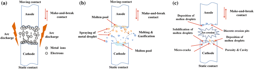 | Fig. 8 Arc erosion model of Cu-0.23Be-0.84Co alloy in make-and-break contact: a the high-speed movement of metal ions and electrons, and intense collision with cathode and anode in discharge channel; b the melting and gasification of contact material, formation of molten pool and spraying of molten droplets; c the solidification of metal, deposition of molten droplets and formation of discrete erosion pits, molten droplet, porosity and cavity, microcracks, etc. on contact surfaces |
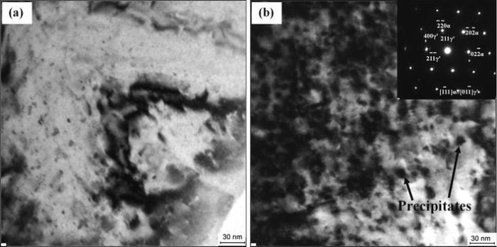
The characteristics and mechanism of arc erosion are very complex. Based on the same parameters of electrical, mechanical and environmental, the material parameters have an obvious effect on arc erosion of contacts. As can be seen from the contact surface morphology after arc erosion (see Figs. 3, 4, 5, 6, 7), the heat and energy generated from arc root intensively release on the surface and near surface layer of contacts. Therefore, for the contact material of Cu-0.23Be-0.84Co alloy, its ability of arc erosion resistance is closely related to the microstructure and properties. Figure 9 shows TEM images of Cu-0.23Be-0.84Co alloy in solution state and aging state, respectively. Figure 9a shows that, after solution treatment at 950 ° C for 1 h, the solute atoms fully dissolve in the Cu matrix and form α supersaturated solid solution by rapid cooling. A large amount of vacancies are formed in the crystal. The integrity of matrix lattice is damaged severely and increases the scattering of electron wave, and then leads to the increase in resistivity of Cu-0.23Be-0.84Co alloy [35, 36, 37]. In addition, the hardness is lower due to almost nonexistent precipitates. In the process of electric contact, the temperature rise of contact material in solution state is larger due to lower hardness and electrical conductivity. It easily leads to material melting and gasification and then forms arc erosion morphology with large molten droplets and flocculent or coral structure (see Figs. 4, 5). However, during the subsequent aging process, the solute atoms precipitate from α supersaturated solid solution and form a series of phases. As soon as the Be atoms cluster in α solid solution, the precipitation starts to happen [38, 39]. As shown in Fig. 9b, after aging at 480 ° C for 4 h, the supersaturated solid solution is decomposed, and a large number of Be-enriched γ ′ precipitates with a size of 8-10 nm dispersively distribute in the Cu matrix. The γ ′ precipitates is one of the Be-Cu intermetallic compounds, namely BeCu2. The dissolved atoms in the supersaturated solid solution could trap dislocations during aging process, which significantly increased the dislocation density. And in turn the high-density dislocation supplied abundant nucleus sites for the precipitates [40, 41]. The formation and growth of γ ′ phases lead to the strong lattice distortion field around the precipitates. The arc erosion resistance primarily mainly depends on the composition (structure), morphology, size and distribution of the precipitates dissolved from the supersaturated solid solution after aging treatment. During the electrocorrosion processes, the γ ′ precipitates can effectively reduce the mass loss of contact materials and improve the surface damage. The formation γ ′ phase is responsible for the improvement of performance of Cu-0.23Be-0.84Co alloy, especially for the arc erosion resistance.
 | Fig. 9 TEM images of Cu-0.23Be-0.84Co alloy in solution state and aging state: a solution treatment at 950 ° C for 1 h; b aging at 480 ° C for 4 h |
In this study, the arc erosion behavior of Cu-0.23Be-0.84Co alloy in solution state and aging state was experimentally investigated. The changes in arc duration, arc energy, contact resistance and contact pressure of Cu-0.23Be-0.84Co alloy in solution state and aging state during make-and-break contacts were revealed. The materials transfer from anode to cathode during make-and break contacts. The total mass loss is closely related to the splash of metal droplets, the evaporation of the metal vapors, the transfer of metals between anode (moving contact) and cathode (static contact). The discrete corrosion pits, molten droplet, porosity and cavity distribute on the surface of moving contact and static contact. In addition, the arc erosion model of Cu-0.23Be-0.84Co alloy in make-and-break contact was built. It is concluded that the characteristic parameters of arc discharge and the arc erosion morphology and then the arc erosion resistance of Cu-0.23Be-0.84Co alloy are closely related to the microstructure and properties of contact materials. Therefore, this experimental study is important to evaluate the anode or cathode electrocorrosion fatigue life. It can provide a certain reference for the selection and design of contact materials.
This work was financially supported by the State Key Program of the National Natural Science Foundation of China (No. U1502274), the Innovation Scientists and Technicians Troop Construction Projects of Henan Province (No. C20150014), the Program for Innovation Research Team (in Science and Technology) in University of Henan Province (No. 14IRTSTHN007) and the Project of Luoyang Science and technology development (No. 1401055A).
The authors have declared that no competing interests exist.
| [1] |
|
| [2] |
|
| [3] |
|
| [4] |
|
| [5] |
|
| [6] |
|
| [7] |
|
| [8] |
|
| [9] |
|
| [10] |
|
| [11] |
|
| [12] |
|
| [13] |
|
| [14] |
|
| [15] |
|
| [16] |
|
| [17] |
|
| [18] |
|
| [19] |
|
| [20] |
|
| [21] |
|
| [22] |
|
| [23] |
|
| [24] |
|
| [25] |
|
| [26] |
|
| [27] |
|
| [28] |
|
| [29] |
|
| [30] |
|
| [31] |
|
| [32] |
|
| [33] |
|
| [34] |
|
| [35] |
|
| [36] |
|
| [37] |
|
| [38] |
|
| [39] |
|
| [40] |
|
| [41] |
|