


Joint Characteristics and Corrosion Properties of Bypass-Current Double-Sided Arc-Welded Aluminum 6061 Alloy with Al-Si Filler Metal
[Yu-Gang Miao, Ben-Shun Zhang, Bin-Tao Wu, Xiao-Xiao Wang, Guang-Yu Chen, Duan-Feng Han ]
]
]
|
|


Sheets of aluminum 6061 alloy were welded using bypass-current double-sided arc welding with Al-Si filler wire to investigate the effect of Al-Si intermetallic compounds on the microstructure, microhardness and corrosion behavior of weld joint. Experimental results indicated that the Al4.5FeSi phase in the topside of the weld joint was finer than that in the backside and newly formed phase of Al0.5Fe3Si0.5 was observed in the backside. The formation of reinforcing phases of Al-Fe-Si in the weld improved the microhardness of the weld by about 18%. The corrosion resistance of the weld zone was greater than that of the base metal, while the corrosion current displayed opposite, and the corrosion resistance of the weld region was better than that of the base metal.
Diverse applications of aluminum alloys in automobile and aerospace industries dictate significance of choosing their assortment based on welding behavior plus selection of most suitable welding method [1]. Aluminum 6061 alloy has been widely applied, because of its good mechanical properties, chemical stability and acceptable corrosion resistance [2, 3].
Advanced welding methods have been used to joint mid-thickness sheets of aluminum alloy to a desired thickness. For instance, laser welding is widely used in industrial production because of its advantages, such as low heat input and high welding speed [4]. Friction stir welding can be used to improve the corrosion behavior of metals [5]. However, some of them also have the problems of inefficiency and energy consumption, such as chamfering and edge planning. In order to increase the weld penetration without substantial cost increase, Zhang et al. [6] proposed double-sided arc welding (DSAW) process, by directly connecting the two torches to the two terminals of a single power supply and placing them on the opposite side of the workpiece to force the current flow through the thickness and used bypass-current double-sided arc welding (BC-DSAW) which has deeper penetration and higher welding speed than DSAW process in join mid-thickness plate to eliminate the weld depression in DSAW process [7].
As a significant factor for a welded joint, corrosion behavior has been paid much attention for specific application [8]. Previous studies show that corrosion resistance of the welded materials has different corrosion resistances in different welding regions, and the welded zones of most joints are susceptible to corrosion [9]. So, Al-Si-x series filler wire has been adopted to improve the mechanical properties and corrosion resistance of aluminum alloy weld [10, 11].
In the present study, 6-mm-thick aluminum 6061 alloy was welded using BC-DSAW process with Al-Si filler metal. The relationship between seam appearance and arc behavior was discussed, and the effects of Si contents on joint reliability were investigated by measuring joint microhardness and characterizing interfacial microstructures and corrosion behavior.
For the present study, the base metal used was aluminum 6061 alloy sheets with dimension of 200 mm × 50 mm × 6 mm, and the chemical composition of the alloy is given in Table 1. The filler material used was Al-Si alloy wire of 1.2 mm in diameter and the chemical composition of it was tested by X-ray fluorescence (XRF) spectrum analysis, which are also given in Table 1. Prior to welding, the surfaces of specimens were degreased in acetone and ground with grit paper to remove the oxide layer. BC-DSAW method was used to weld specimens, and argon with purity of 99% was used as the shielding gas. Figure 1illustrates the schematic diagram of BC-DSAW process, and the main welding parameters are listed in Table 2.
| Table 1 Chemical composition of aluminum 6061 alloy and 4043 filler metal (in wt%) |
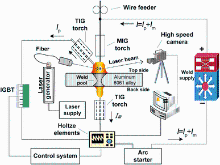 | Fig. 1 Schematic diagram of BC-DSAW process |
| Table 2 Welding parameters used for current study |
Test specimens were prepared by sectioning, grounding and polishing after welding. The interface morphology and microstructure of joint samples were characterized by optical microscopy (OM, Keyence VHX-1000) and scanning electron microscopy (SEM, FEI Quanta 200). The phase constituent of Al-Si weld was analyzed by X-ray diffraction (XRD, Bruker D8 Advance).
Rockwell hardness test was conducted as required in ASTM 18-05 standard. The microhardness from the base metal to the weld interface was measured using HXD— 1000 TM microhardness tester with a load of 0.98 N for 15 s.
To compare the corrosion behaviors of base metal (BM) and weld zone (WZ), an electrochemical corrosion test was performed independently by separating these zones from the weld joint. While potentiodynamic polarization method was applied using a potentiostat (electrochemical impedance analyzer) interfaced with a computer, and a three-electrode cell with the sample with an exposed area of 1 cm2 was used as the working electrode. A saturated calomel solution was used as the reference electrode (SCE), and two graphite rods were applied as the counter electrodes [12]. Electrochemical impedance spectroscopy (EIS) measurements were taken using AC signal with an amplitude of 10 mV peak to peak in the frequency range of 100 kHz to 10 mHz [13], by scanning from low frequency to high frequency with a speed of 0.01 V/s and a standing time of 2 s. Both curves were recorded in 0.5 wt% NaCl solution at room temperature of approximately (25 ± 1) ° C.
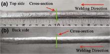
As shown in Fig. 2, the stable process without obvious welding spatters was obtained with MIG-TIG coupled arc burning on topside and TIG arc burning on backside. The stability of the welding process was improved by adding a bypass torch to increase the stability of arc and to reduce welding defects such as spatters and cracks. In the BC-DSAW process, part of MIG current flows back to the power source through the bypass torch and the remaining part flows to the root-sided TIG torch through the base metal. Thus, the filler wire is melted by high current to achieve high deposition rate and stable droplet transition, while the arc pressure and the heat input into the base metal are reduced [14]. Consequently, only a small current flows through the root-sided TIG torch to reduce the burning loss of electrode and to improve the bearing capacity. Meanwhile, the mutual attractive effect between the face-sided arc and the root-sided arc guarantees the concentration of energy required to ensure the weld penetration.
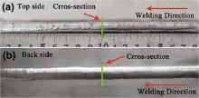 | Fig. 2 Appearance of aluminum alloy joint made by BC-DSAW: a topside; b backside |
Figure 3 shows the representative cross section of the joint produced by bypass-current MIG welding (BC-MIG) and BC-DSAW. It can be seen that the full penetration joint was obtained when the background power line was replaced with TIG torch, as shown in Fig. 4. The X-shaped weld zone was obviously gained after solidification of liquid melt on the either side of aluminum alloy base metal with filler wire under heat source at topside and backside. It was also found that there was a kind of mutual attractive effect between the two arcs located on either side of the based metal, and so, the arc energy was more concentrated along the thickness of the base metal, which helps the formation of a full penetration. Furthermore, the energy density is normally distributed from the edge to center of the arc itself [15]. On the other hand, as shown in Fig. 3b, there was greater energy near the center of arc. The depth of molten pool cannot be further increased because of the less heat on the edge of arc, which leads to the X-shaped morphology of cross section.
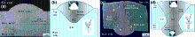 | Fig. 3 Cross sections of BC-MIG and BC-DSAW: a morphology of BC-MIG; b distribution of arc energy by BC-MIG; c morphology of BC-DSAW; d distribution of arc energy for BC-DSAW |
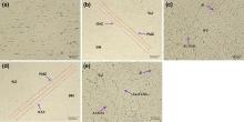 | Fig. 4 Microstructures of different regions of weld joint as marked by A, B, C, D and E in Fig. 3c: a region A; bregion B; c region C; d region D; e region E |
The SEM morphologies of different zones marked as zones A, B, C, D and E in Fig. 3a are presented in Fig. 4. As shown in Fig. 4b, d, there are four different zones: base metal (BM), heat-affected zone (HAZ), partially melted zone (PMZ) and weld zone (WZ). The base metal consists of α -Al glable, as shown in Fig. 4a, the irregular eutectic of the cast material was covered into spheroidized Si particles due to the solution treatment [16]. It is also found that the primary silicon particles and the dendritic-like structure with many equiaxed grains were uniformly formed in the weld zone after the melting of the alloy. As shown in Fig. 4c, e, the eutectic structure of the weld on the topside is more uniformly distributed than the weld on the backside, which is due to the larger heat input produced at the topside under the coupling arc. The partially melted zone contains coarse columnar Al solid grains Al4.5FeSi Al5FeSi and Al0.5Fe03Si0.5 eutectic structures, which are due to the higher cooling rate [17].
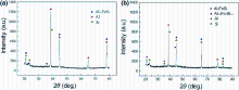
As shown in Fig. 5, Al4.5FeSi and primary Si are detected at the topside of the cross section, which suggested that enhanced phase β (Al-Fe-Si phases) was formed in the local area due to the gathering of Fe and Si atoms after the filler wire was heated and cooled. Accordingly, the remaining eutectic structure is identified as Al0.5Fe3Si0.5 at the backside of the cross section. The different phases of the same intermetallic compound are related to the heating and cooling of the filler wire during the welding, and similar result was presented in Ref. [18]. In the DSAW process, the crystallization of liquid filler wire was under non-equilibrium conditions, the heating and cooling of the filler wire was resulted in at the topside, and the formation of larger grain occurred in the weld. So, the different phases of the same intermetallic compound were coarsened at the topside and the backside of the weld cross section.
 | Fig. 5 XRD patterns for different weld zones: a upper region; b lower region |
As shown in Fig. 6a, the weld hardness is improved by about 128 HV, and the hardness of heat-affected zone and base metal basically equal to the average of about 105 HV, because the reinforced β phases which consisted of Al, Fe and Si elements of filler metal are uniformly distributed in the matrix and grain boundaries after the filler wire was melted and solidified with base metal. In addition, the additional Si elements in the weld zone increase the microhardness of intermetallic compounds because the Si element itself has a high wear resistance. As shown in Fig. 6b, the hardness is improved by about 142 HV on the top of the weld, and the weld hardness is clearly lower at the root of the joint, because additional Si elements in the top weld zone increase the microhardness of intermetallic compounds.
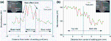 | Fig. 6 Microhardness for different welding zones: a along base metal to weld zone; b along top to root of weld zone |
3.4.1 Potentiodynamic Polarization
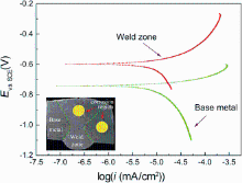
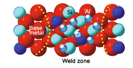
As shown in Fig. 7 and Table 3, the base metal has the corrosion potential (E) of -741 mV and the corrosion current density (i) of 0.2407 μ A/cm2. The corrosion potential of weld zone increases to -597 mV while its current density decreases to 0.1862 μ A/cm2. After upon the completion of the BC-DSAW process, the corrosion potential of the weld zone moves toward a positive value to demonstrate a passive behavior. It is also found that the corrosion potential notably shifts toward a nobler state with an increase in Si-rich passes. In addition, the icorr of weld zone is much lower than the icorr measured for the base metal. As shown in Fig. 7 and Table 3, the corrosion resistance of base metal is less than that of the weld zone, which means that the small grains with Si particles formed in the weld region results in the corrosion behavior better than that of the base metal. Similar conclusions on the effects of the microstructure on the corrosion rate were also reported on welded Al alloy with Al-Si filler wire by Changa et al. [19] and Song et al. [20]. Previous study showed that the refinement of intermetallic compounds grain, eutectic and primary silicon particle sizes provides not only larger nucleation sizes for the formation of thicker and denser oxide film on the surface of weld region, but also larger cathodic area for diffusion of oxygen ions, which results in a lower corrosion rate [13, 21]. As shown in Fig. 8, in the corrosion process with NaCl electrolyte solution, the Cl particle could be adsorbed largely on the boundary between Si particles and Al particles [13], which hinders the electrochemical reaction of Al atoms in the anode of galvanic cell and decreases the molecular fracture speed and internal atomic recombination rate, which effectively lowers the weld region corrosion rate. On the other hand, the formation of phase β lattice on the Si rich of weld zone is evident from the positive shift of corrosion potential, reduction in corrosion current and increased cathodic area (Si area).
 | Fig. 7 Cyclic polarization cures of weld zone and base metal in 0.5 wt% NaCl solution at (25 ± 1) ° C |
| Table 3 Electrochemical parameters derived from potentiodynamic polarization plots of Fig. 7 |
 | Fig. 8 Schematic diagram of Si, Al and Cl particles positions in 0.5 wt% NaCl solution |
3.4.2 EIS Measurements
Figure 9 presents the Nyquist diagram for the weld zone and the base metal in 0.5 wt% NaCl solution at Ecorr and temperature of (25 ± 1) ° C. It can be found that the smallest semicircles are obtained for the base metal and the biggest semicircles for the weld zone. The semicircles diameter increases with the size of silicon particles. It can be indicated that the resistance of weld zone is greater than that of the base metal. In the corrosion process with NaCl solution, the anode activation is not in sufficient because of the increasing silicon particle in the weld zone, which leads to a radius of capacitive loop larger than that of the base metal. Furthermore, the corrosion stage of the EIS equivalent circuit diagram was established according to the EIS spectra. As shown in Fig. 10, the polarization resistance value of the weld zone with Al-Si wire is greater than that of the aluminum base metal, which means that the corrosion rate of the weld zone is lower than that of the base metal.
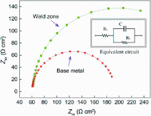 | Fig. 9 Nyquist diagram for weld zone and base metal in 0.5 wt% NaCl solution at (25 ± 1) ° C |
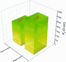 | Fig. 10 Polarization resistance value of weld zone and base metal from EIS simulation |
It is found through analysis that due to the increase of nonmetal elements Si in the weld zone, the difference in equilibrium potential between intermetallic phase particles becomes significant. In addition, the amount of intermetallic phase particles in per unit area of weld region is much less than that in the base metal region. As a result, the number of electrochemical corrosion reactions occurred in per unit area of weld zone is less than that occurred in the base metal region in the corrosion process, and so, the polarization resistance in weld zone is greater than that in the base metal region. Meanwhile, there is a difference between current density, potential and resistance of microcell circuit in the corrosion process, which may lead to a difference in the corrosion rate.
1)BC-DSAW process could be used to obtain uniform appearance and full penetration on the cross section of aluminum alloy joint. And the stability of welding process could be obviously improved by adding a bypass arc.
2)The eutectic structure of the weld zone on the topside is finer than that on the backside, which could be attributed to the varied heat input on the molten pool. It is found through XRD analysis that Al4.5FeSi and primary Si phase are supposed to be in the topside of the weld, which means that enhanced phase β (Al-Fe-Si phases) is formed in the local area, while the remaining eutectic structure is identified as Al0.5Fe3Si0.5 on the backside of the weld.
3)Due to the increasing silicon particle in the weld zone, the microhardness of weld zone is 18% higher than that of the base metal, which results in the formation of uniform Al-Si-Fe intermetallic compounds inside of the joining zone.
4)The corrosion rate of base metal is lower than that of the weld zone because the silicon particle is protected by the weld region against possible corrosion. Higher charger transfer resistance is presented on EIS plots for weld zone.
This work was financially supported by the National Natural Science Foundation of China (No. 51005049).
The authors have declared that no competing interests exist.
作者声明: 无竞争性利益关系
| [1] |
|
| [2] |
|
| [3] |
|
| [4] |
|
| [5] |
|
| [6] |
|
| [7] |
|
| [8] |
|
| [9] |
|
| [10] |
|
| [11] |
|
| [12] |
|
| [13] |
|
| [14] |
|
| [15] |
|
| [16] |
|
| [17] |
|
| [18] |
|
| [19] |
|
| [20] |
|
| [21] |
|