


Effect of Cooling Rate on Microstructure and Mechanical Properties of 20CrNi2MoV Steel
[Jian Zhang1 , Chang-Sheng Li1  , Bin-Zhou Li
1 , Zhen-Xing Li1 , Xue-Dong Pang2 ]
, Bin-Zhou Li|
|


Thermo-mechanical process and continuous cooling process were carried out on 20CrNi2MoV steel. Three cooling rates were implemented to optimize the mechanical properties. The microstructure evolution, precipitation behavior, and strengthening mechanisms were systematically investigated, and the fracture mechanisms were analyzed via combination of impact fracture morphologies and deflection-load curves. The experimental results indicate that the transformed microstructure of experimental steel is all complex consisting of granular bainitic ferrite and bainitic ferrite with dispersed martensite/austenite (M/A) constituents in the matrix at cooling rates of 13, 21, and 29 °C/s. When the cooling rate increases, the grain of the steel is obviously refined. The sizes of the bainitic ferrite are 5.8, 4.7, and 3.1 μm under cooling rates of 13, 21, and 29 °C/s, respectively. The refinement of the bainitic ferrite plays a dominant role in strength increasing and also contributes to high crack propagation energy. However, the morphologies of M/A constituents obtained under different cooling rates contribute to different crack initiation energies and then affect the impact property.
The well-known productions of high-strength toughness steel, in general, are performed by continuous cooling processes such as normalizing, quenching, and accelerate cooling [1, 2, 3, 4, 5]. The microstructure, therefore, is composed of a mixture of various kinds of transformation products such as the martensite, the bainite, and the ferrite [6, 7]. Above all, the bainite plays an important role in improving strength and toughness [8, 9]. However, the toughness of the bainitic transformation products is not always monotonically dependent on the cooling rate and there is an optimum cooling rate for high toughness [10, 11, 12, 13].
In recent years, the 20CrNi2MoV steel has received significant attention because of applications in abrasion and impact resistant parts [14, 15, 16], and now it is widely employed in super impact resistance and abrasion parts for large machinery and equipment, e.g., high-speed railway train bearings. Also the bainite in the 20CrNi2MoV steel with good strength and toughness is the subject of debate. And in the circumstance of energy saving and emission reduction all over the world, further reasonable application and improving the strength and toughness of the bainitic steel through the proper cooling process are becoming an urgently needed solution [17, 18, 19, 20].
Accelerate cooling processing is a widely acknowledged approach to optimize strength-toughness combination through optimization of cooling parameters. In the present work, the effect of cooling rates on the microstructure and mechanical properties of 20CrNi2MoV steel were investigated. Microstructure characteristics of the experimental steel with various cooling rates were clarified. The mechanism of brittleness and toughness based on cracks initiation and cracks propagation was systematically elucidated in details.
The experimental steel ingot was produced by vacuum melting and electroslag remelting. The chemical composition of the steel in wt% was 0.2C, 0.58Si, 0.52Mn, 0.008P, 0.003S 0.35Cr, 0.24Mo, 1.45Ni, 0.38Nb, and 0.59 V. The ingot was forged into slabs with the dimensions of 60 mm × 60 mm × 180 mm. The slab was heated to 1200 ° C for 3 h to dissolve the microalloying elements and roughly rolled to 27 mm at 1100-1150 ° C. After air cooling to 890 ° C, followed by rolling using four passes on Φ 450 mm trial rolling mill, the slab was rolled to a plate of 12 mm thickness. The end temperature of finish rolling was controlled at 860 ° C. And then the plate was subjected to two-stage continuous cooling. In the first stage, it was water-cooled at a rate of 10-30 ° C/s to final cooling temperature from 510 to 530 ° C. In the second stage, the plate was air-cooled to room temperature.
Metallographic specimens were mechanically polished and etched with a 4 vol% nital and observed using Zeiss Ultra55 scanning electron microscope (SEM). The fracture surface of impact specimens was studied by an FEI Quanta 600 SEM. Transmission electron microscopy (TEM) studies were conducted using 3-mm-diameter thin foils, electropolished using a solution of 8 percent perchloric acid and alcohol and examined by FEI TecnaiG2 F20 TEM at an accelerating voltage of 200 kV. The chemical composition of the precipitates was determined by energy-dispersive X-ray spectroscopy (EDX).
Tensile specimens of dimensions of 5 mm in diameter and gauge of 25 mm in length were machined from the plates parallel to the rolling direction. The tensile tests were detected at room temperature with a crosshead speed of 1 mm/min using a Shimadzu AG-X universal testing machine. Charpy V-notch impact tests were performed at 20 ° C using standard specimens (dimensions: 10 mm × 10 mm × 55 mm) with a V-notch parallel to the rolling direction using Instron Dynatup 9200 series instrumented drop weight impact tester, consistent with ASTM E23 specification. All the strength and toughness values obtained here are an average of three measurements.
Transformation temperatures were determined by tangents method. Draw tangent at catastrophe point in dilatometric curves and the point which tangent began to deviate from the curve is defined as critical point. Figure 1 shows the CCT diagram for the 20CrNi2MoV steel. It can be seen from Fig. 1 that transformation of the ferrite and the bainite occurs for the experimental steel proceeds separately. That is mainly because the steel is rich in Cr, Ni, Mo, and V which can increase the stability of supercooled austenite and the incubation time of phase transformation.
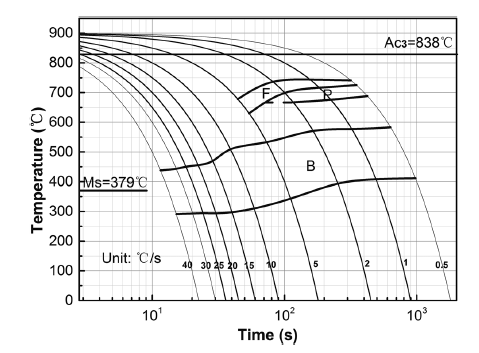 | Fig. 1 Deformed austenite CCT diagram of the experimental steel |
According to the CCT curves in Fig. 1, if only the bainite structure of the experimental steel was expected to be obtained, the cooling rate needs to be 10-30 ° C/s, so that transformation of the austenite to the ferrite and the martensite is restrained. In the current study, the cooling path after final hot rolling is indicated in red line in Fig. 1.
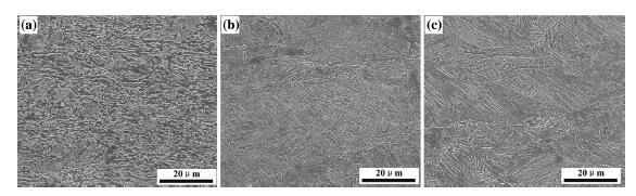
SEM micrographs of the experimental steel at different cooling rates are presented in Fig. 2, which reveal an evolution of the microstructure as the cooling rate increases from 13 to 29 ° C/s. As can be seen from Fig. 2, the transformed microstructure of experimental steel with different cooling rates is all complex consisting of the granular bainitic ferrite (GF), the bainitic ferrite (BF), and the dispersed M/A constituents in the matrix where the martensite/austenite (M/A) is a significant structural characteristic in the microstructure of the bainite, and it generally exists in bainitic ferrite grain boundary or between neighboring ferrite laths. Here the magnification of the micrograph is slightly low and cannot clearly observe the independent martensite/austenite constituent. While in the following section of this paper, the martensite/austenite constituent has been observed by TEM.
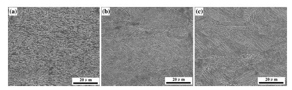 | Fig. 2 SEM images of hot rolling test steels at different cooling rates: a 13 ° C/s, b 21 ° C/s, and c 29 ° C/s |
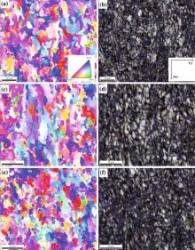
Figure 3 shows EBSD results of experimental steel at different cooling rates. The colors in Figs. 3a, c, e represent the crystallographic orientation normal to the observed plane, as indicated by the stereographic triangle in the inset. Comparing Fig. 3a with c, it can be found that the specimen with the cooling rate of 13 ° C/s presents more homogeneous and finer orientation distribution than that with the cooling time 21 ° C/s based on the distribution of orientation colors. As shown in Fig. 3a, the bainitic block with nearly the same trace direction in the morphology normally contains several laths in the crystallography for the specimen at the cooling rate of 13 ° C/s. However, as the cooling rate increases, the size of the bainitic block refines and the boundary turns clear (shown in Fig. 3c) though it contains highly intricate, finer, and thinner of the laths in the morphology. When the cooling rate increases up to 29 ° C/s (Fig. 3e), the austenite grain boundaries and deformation bands increase gradually and the ferrite transformation nucleation points increase which lead to the following fine grain forms.
 | Fig. 3 Crystallographic characteristics of experimental steels analyzed by EBSD: a, c, e orientation image maps of experimental steel at different cooling rates 13, 21, and 29 ° C/s correspondingly; b, d, f image quality maps with the grain boundary mis-orientation distribution of experimental steel at different cooling rates 13, 21, and 29 ° C/s correspondingly |
In the boundary maps (Figs. 3b, d, f), the blue lines are the high misorientation grain boundaries higher than 15° , while the red lines stand for the low misorientation grain boundaries from 2° to 15° . The grain boundaries of the block of the ferrite laths (e.g., the boundary of deformed austenite) exhibited high misorientation grain boundaries, and the laths inside the austenitic grains had low misorientation grain boundaries. The high misorientation grain boundaries efficiently arrest the propagation of cleavage microcracks, and it can be regarded as the effective grain size which controlled the growth of crack. The low misorientation boundaries cannot significantly deflect the cleavage cracks. However, it is the effective grain boundary contributes to the strength of the experimental steel. And the grain size and width of the bainitic ferrite laths have significant impacts on the strength.
Figure 4 shows the grain size distribution of experimental steels on different cooling rates, the bainitic ferrite presents various nonequiaxed grain sizes distributed in a random manner, and grain refinement is obtained accompanied by increasing cooling rate. The sizes of bainitic ferrite are 5.8, 4.7, and 3.1 μ m under different cooling rates of 13, 21, and 29 ° C/s, respectively.
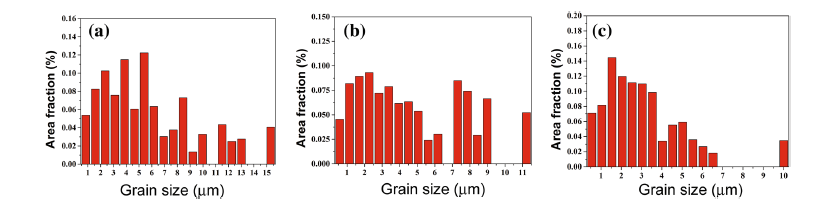 | Fig. 4 Grain size distribution of experimental steels of different cooling rates: a 13 ° C/s, b 21 ° C/s, and c 29 ° C/s |
Figure 5 shows TEM micrographs of the experimental steel under different cooling rates. There is high density of dislocations in the matrix of the bainitic ferrite. The bainitic ferrite block consists of several parallel sub-plates with the width of 0.3, 0.2, and 0.17 μ m under different cooling rates of 13, 21, and 29 ° C/s, respectively, as shown in Fig. 5a-c. The morphology of M/A constituents in the bainite under different cooling rates is also investigated. There are three types of M/A constituents were observed: (1) rodlike M/A constituent with diameter of 0.5 μ m (Fig. 5b) under the cooling rate of 13 ° C/s reduces the stress concentration and then prevents cracks from propagation; (2) fine film M/A constituent distributes between the ferrite laths with length of 0.5 μ m and width of 50 nm under the cooling rate of 21 ° C/s (Fig. 5c); and (3) ultrafine film or acicular M/A constituent distributes between the fine ferrite laths with the diameter of 0.15 μ m (Fig. 5c) under the cooling rate of 29 ° C/s.
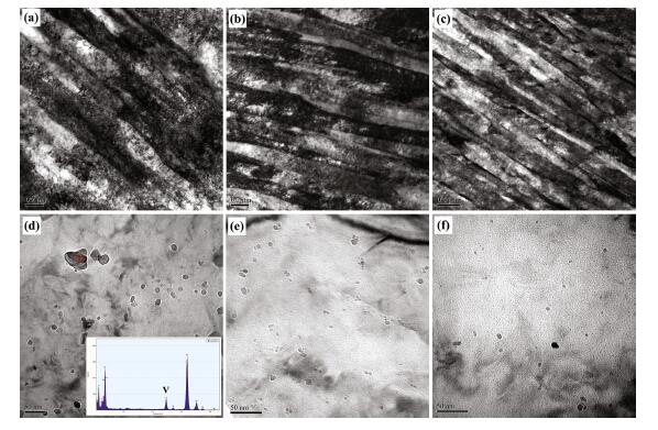 | Fig. 5 TEM images of experimental steels at different cooling rates: a, d 13 ° C/s, b, e 21 ° C/s, and c, f 29 ° C/s |
Figures 5d, e, and f show the precipitates morphologies of the steel under different cooling rates. The energy spectrum analysis is shown in Fig. 5d (insert), and the result illustrates that the precipitates are the compounds of V(C, N). The particle size of the precipitates is about 25 nm, 15 nm, and 8 nm under the cooling rate of 13, 21, and 29 ° C/s, respectively. With the increase in the cooling rate, the particle size and amounts of the precipitates decrease.
The mechanical properties of the experimental steels under different cooling rates are shown in Fig. 6. The results are also summarized as follows. Under the cooling rate of 13 ° C/s, the yield strength, the tensile strength, and elongation to fracture of the steel were 803, 997 MPa, and 18.4%, respectively. The impact absorbed energy of Charpy specimens tested at room temperature was 109 J. Under the cooling rate of 21 ° C/s, both the yield strength and the tensile strength were increased to 879 and 1046 MPa, respectively, while the elongation to fracture was decreased to 16.6%, and the impact absorbed energy at room temperature was reduced to 88 J. Under the cooling rate of 29 ° C/s, both yield strength and the tensile strength were slightly increased to 894 and 1086 MPa, while the elongation to fracture was sharply decreased to 13.6% and the impact absorbed energy at room temperature only reached to 50 J. In general, the combination of strength and ductility of experimental steel decreases with the increase in cooling rate.
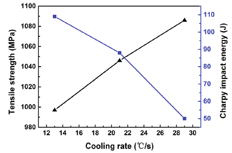 | Fig. 6 Mechanical properties of the experimental steel under different cooling rates |
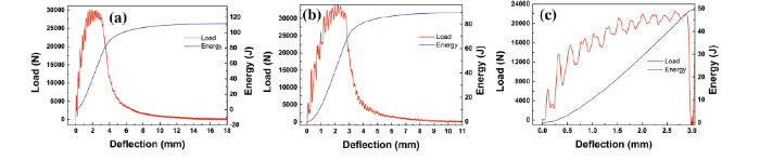
Figure 7 shows the deflection-load and deflection-energy plots of impact specimens. The total absorbed energy can be divided into E1-crack initiation energy (including Ee-elastic deformation energy and Ep-plastic deformation energy), E2-stable crack propagation energy, and E3-unstable fracture energy.
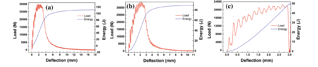 | Fig. 7 Deflection-load and deflection-energy plots of impact specimens: a 13 ° C/s, b 21 ° C/s, and c 29 ° C/s |
E1 has a relationship with the initiation and propagation of the plastic shear zone and represents the difficulty of initiating the crack. As shown in Figs. 7a-c, the loads all reach peak value at the similar deflection (~ 2.7 mm) in the three deflection-load plots, and the crack initiation energy is about 53 J.
E2 is connected with the propagation of the stable crack, namely the tearing energy of the fracture fibrous zone. Once the unstable crack begins to develop, the stable cracks stop propagating. Therefore, E2 reflects the difficulty of initiating and prorogating the unstable crack. E3 represents the fracture energy of the hardened zone, which usually depends on the restraint of the unstable crack. Under the cooling rate of 13 ° C/s, the total impact absorbed energy of 109 J at room temperature is separated into the crack initiation energy, stable crack propagation energy, and unstable fracture energy which are 53, 39, and 17 J, respectively, and for the steel under the cooling rate of 21 ° C/s are 51, 21, and 16, respectively. While under the cooling rate of 29 ° C/s, there is only the crack initiation energy about 50 J and the crack propagation process was disappeared. Thus, similar crack initiation energies were obtained in the steel under the cooling rate of 13, 21, and 29 ° C/s, while the crack propagation energy of the steel under the cooling rate of 13 ° C/s was significantly higher than the steel of 21 ° C/s. The refinement of the bainitic ferrite plays a dominant role in the formation mechanism of crack and contributes to high crack propagation energy, while the morphologies of M/A constituents obtained under different cooling rates contribute to different crack initiation energies. Furthermore, the loads of the steel under the cooling rate of 13 and 21 ° C/s decrease gradually after attaining the peak, whereas in the steel under the cooling rate of 29 ° C/s, the load decreases sharply, and the brittle fracture characteristic is observed.
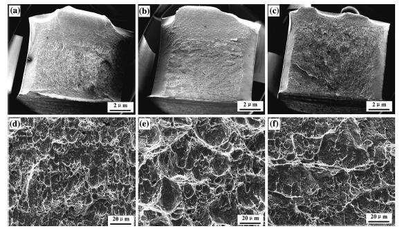
Figure 8 shows the SEM micrographs of the impact fracture at room temperature. Except for the V-notch zone, the fracture surface can be divided into three zones, including the fibrous zone, the radial zone (zone extending outwards), and the shear lip zone. During the Charpy impact process, the fibrous zone can absorb higher impact energy, and its area proportion of the sectional area reflects the toughness value. By observing the macroscale fracture, as shown in Figs. 8a-c, the surface of the steel under the cooling rate of 13 and 21 ° C/s consists of several distinct regions, while the steel under the cooling rate of 29 ° C/s has hardly any fibrous zone. The steel under the cooling rate of 13 ° C/s represents the maximum area of fibrous zone consisting of elongated small dimples (Fig. 8a). The fibrous zone of the steel under the cooling rate of 21 ° C/s comprises of large and flat dimples (Fig. 8b). Compared to Fig. 8a, as the cooling rate increases, the impact energy of the steel under the cooling rate of 21 ° C/s is reduced. However, large cleavage facets exist in the radial zone of the steel under the cooling rate of 29 ° C/s (Fig. 8c), which can absorb negligible impact energy, and thus, it presents an apparent brittle fracture characteristics.
 | Fig. 8 SEM images of the impact fracture: a, d 13 ° C/s, b, e 21 ° C/s, and c, f 29 ° C/s |
1.The microstructure of 20CrNi2MoV steel consists of granular bainitic ferrite and bainitic ferrite with dispersed martensite/austenite constituents in the matrix. When the cooling rate increases, the ferrite grain is obviously refined. The bainitic ferrite size is 5.8, 4.7, and 3.1 μ m under cooling rates of 13, 21, and 29 ° C/s, respectively.
2.With increasing cooling rate, the yield strength and the tensile strength of the 20CrNi2MoV steel increase, while the ductile decreases. The yield strength is 803, 879, and 894 MPa, the tensile strength is 997, 1046, and 1086 MPa, and the elongation to fracture is 18.4, 16.6, and 13.6%, under the cooling rate of 13, 21, and 29 ° C/s, respectively. In general, the steel exhibits better strength and ductility which satisfy the expected requirements when the cooling rate is less than 21 ° C/s.
3.The refinement of the bainitic ferrite plays a dominant role in the formation mechanism of the crack and contributes to high crack propagation energy, while the morphologies of M/A constituents obtained under different cooling rates contribute to different crack initiation energies. Under the cooling rate of 13 ° C/s, initiation energy is 53 J, stable crack propagation energy is 39 J, and unstable fracture energy is 17 J. Under the cooling rate of 21 ° C/s, initiation energy is 51 J, stable crack propagation energy is 21 J, and unstable fracture energy is 16 J. While the cooling rate is 29 ° C/s, there is only the crack initiation energy about 50 J and the crack propagation process is disappeared.
4.Increasing cooling rate is the very effective approach for increasing the great strength but decreasing the toughness, whereas when the cooling rate is controlled to 20 ° C/s, the experimental steel would exhibit better the strength and the toughness properties, which satisfy the expected requirements.
This work was financially supported by the National High Technology Research and Development Program of China (No. 2012AA03A503), the National Natural Science Foundation of China (Nos. 51174057 and 51274062) and Research Fund for the Doctoral Program of Higher Education of China (No. 20130042110040).
The authors have declared that no competing interests exist.
| [1] |
|
| [2] |
|
| [3] |
|
| [4] |
|
| [5] |
|
| [6] |
|
| [7] |
|
| [8] |
|
| [9] |
|
| [10] |
|
| [11] |
|
| [12] |
|
| [13] |
|
| [14] |
|
| [15] |
|
| [16] |
|
| [17] |
|
| [18] |
|
| [19] |
|
| [20] |
|