Molecular Dynamics Simulations of the Orientation Effect on the Initial Plastic Deformation of Magnesium Single Crystals
Qun Zu1, Ya-Fang Guo1, Shuang Xu2, Xiao-Zhi Tang1, Yue-Sheng Wang1
1 Institute of Engineering Mechanics, Beijing Jiaotong University, Beijing 100044, China
2 School of Science, Wuhan University of Technology, Wuhan 430070, China
Corresponding Author: Ya-Fang Guo,E-mail:yfguo@bjtu.edu.cn
Abstract

Molecular dynamics simulation is employed to study the tension and compression deformation behaviors of magnesium single crystals with different orientations. The angle between the loading axis and the basal < a> direction ranges from 0° to 90°. The simulation results show that the initial defects usually nucleate at free surfaces, but the initial plastic deformation and the subsequent microstructural evolutions are various due to different loading directions. The tension simulations exhibit the deformation mechanisms of twinning, slip, crystallographic reorientation and basal/prismatic transformation. The twinning, crystallographic reorientation and basal/prismatic transformation can only appear in the crystal model loaded along or near the a-axis or c-axis. For the compression simulations, the basal, prismatic and pyramidal slips are responsible for the initial plasticity, and no twinning is observed. Moreover, the plastic deformation models affect the yield strengths for the samples with different orientations. The maximum yield stresses for the samples loaded along the c-axis or a-axis are much higher than those loaded in other directions.

Keyword: Molecular dynamics simulations; Magnesium; Plastic deformation; Orientation
1 Introduction

It is well known that the plastic deformation mechanisms of metal materials are related to the sample size [1, 2, 3, 4], temperature [5, 6, 7] and strain rate [8, 9, 10, 11] in addition to the intrinsic factors. In particular, the mechanical behavior dominated by orientation effect has attracted increasing attention in recent years [1, 12, 13, 14, 15, 16]. For example, Battaini et al. [15] have reported the effect of the sample orientation on the mechanical properties of commercially pure titanium plate with a transverse split basal texture at room temperature, and a large variation in the flow stress was found due to the sample’ s orientations. The deformation mechanisms of nickel single crystals have been studied by Li et al. [4] via atomistic simulations, which were characterized by massive dislocation activities within a single slip system and a nanoscale deformation twining in an octal slip system. Furthermore, Kim et al. [12] showed that the crystallographic orientation and the sample size are the important elements on tension-compression asymmetry in molybdenum nano-pillars. More recently, Xu et al. [1] explored the effects of the orientation, size and dislocation confinement on the plastic deformation of aluminum nano-pillars, which showed a significant dependence of the dislocation starvation state and the serrated stress-strain response on higher and lower symmetry orientations.

Due to the excellent properties of low density and high strength, magnesium and its alloys have been widely used in aerospace, electronics, mechanical industry and clinical medicine. However, for hexagonal close-packed (hcp) metals, the plasticity is poor owing to the limited slip systems. The orientation effect is a very important factor for deformation behavior to such asymmetric structure. For exploring the deformation mechanisms in magnesium, the compression experiments along c-axis have attracted wide attention [17, 18, 19, 20] and the loadings on the orientations are also concerned in recent published works [20, 21, 22]. Recently, uniaxial nano-compression experiments of Mg and Mg-0.2 wt% Ce pillars with the basal plane oriented 30° to the loading axis displayed the basal plane sliding and extension twinning [22]. In fact, deformation studies of magnesium single crystals have been conducted by using channel-die tests at room temperature since 1968 [17, 23], which revealed that magnesium exhibited the complex deformation behaviors and various deformation modes. Graff et al. [24] simulated the deformation mechanisms of magnesium alloy by finite element simulation, which matched the above channel-die test results [17, 23]. Moreover, the deformation behaviors of magnesium single crystals with five different orientations at fixed nominal column were presented by micro-compression experiments and display the orientation-dependent mechanisms of deformation at the nanoscale [25].

To better understand the plastic deformation behaviors and mechanisms of magnesium and its alloys, atomistic simulations have been employed widely [6, 26, 27, 28]. However, for the molecular dynamic simulations, researches are mostly focused on the deformation behaviors along some specific loading orientations, especially along the c-axis or a-axis. For example, Li et al. [27] studied the twin boundary interfacial structure and the configuration of zonal twinning dislocations for {10 1̅1}< 10 1̅2> twin growth in magnesium at a-axis tension. Guo et al. analyzed the deformation mechanisms at the nanoscale for magnesium single crystals under c-axis compression, showing no compression twins occur at different temperatures [29, 30]. Recently, the twinning-like lattice reorientation, in which the angle between the basal planes of the parent and the deformed regions was close to 90° , was observed via [1 1̅00]-axis compression experiment and simulation by Liu et al. [31, 32]. In order to study the competition between the activation of slip systems and deformation twinning, it is therefore of great importance to investigate the orientation effects on deformation mechanisms in magnesium single crystals.

Here, molecular dynamics simulations are applied to study the tension and compression deformation of magnesium single-crystal nano-pillars with different loading directions. Various initial plastic deformation mechanisms and subsequent microstructure evolution are analyzed and discussed in detail. This work provides a more deep understanding of the competition mechanism of different plastic deformations in magnesium single crystals with different orientations.

2 Simulation Geometries and Methods

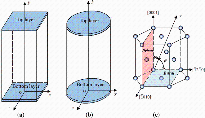
Two perfect single-crystal nano-pillar models with square and circular cross sections (Fig. 1a, b) were established, and the side length and diameter of the samples are about 14.3 and 14.6 nm, respectively. The height-to-side ratio for the square model and length-to-diameter ratio for cylindrical model were both about 2:1. The number of atoms in these two systems was about 280, 000 and 200, 000, respectively. Free boundary conditions were applied in x, y and z directions in simulations. Figure 1c shows a unit cell of the hcp lattice. For the samples with different orientation, the crystal rotated around the [ 1̅010] axis and the loading axis (y) was always perpendicular to the [ 1̅010] axis. The angle (θ ) between the loading direction and the [ 1̅2 1̅0] a-axis ranged from 0° to 90° . In our simulation, ten orientations with different θ of 0° , 10° , 15° , 20° , 31.6° , 45° , 58.4° , 75° , 80° and 90° were examined. The simulations were performed in constant NVT ensemble with a velocity Verlet integrator, and the temperature was controlled at 5 K. The LAMMPS code [33] was used with EAM potentials which were developed by Liu et al. [34] and Sun et al. [35]. The physical properties obtained by these two potentials have been fitted to the data obtained by ab initio method and experiments [36, 37]. The default calculation method in LAMMPS program which is based on the classical statistical mechanics [38, 39] and the virial theorem [40] was adopted to calculate the stress in this work. The AtomEye software [41] was used for visualizing the evolution of the atomistic structures, and the models in Sect. 3 are colored by the Ackland[42].

Fig. 1 a Square, b cylindrical simulation models for magnesium nano-pillars. c The unit cell of hcp lattice. The yaxis indicates the loading direction, which is always perpendicular to the [ 1̅010]-axis

In the simulation, the perfect crystal was relaxed for 30 ps (5000 time steps) at zero force to minimize the potential energy at first. After that, a uniaxial loading was exerted along the y direction by applying a constant strain of about 5 × 10⁷ s-1 on the 1.5-nm-thick top layer, while the 1.5-nm-thick bottom layer was fixed. Then, the system was relaxed for 6 ps before the next increment in tensional/compressive displacement was applied. The simulation was carried out until the maximal strain reached about 10% because the initial plastic mechanism was our concern in this work.

3 Results and Discussion
3.1 Initial Plasticity of Nano-pillar with Different Orientations as Predicted by Liu’ s EAM Potential

Based on the Liu’ s EAM potential, the initial plastic deformation mechanisms of the magnesium single crystals with different orientations under tension and compression are calculated and then listed in Table 1. The results are obtained in the strain range of 0.2% over the yield point. For the square nano-pillars in tension simulations, the first nucleated defects are, respectively, the {10 1̅1} twin, prismatic < a> dislocation, shear band and pyramidal dislocation, when θ < 15° , 15° < θ < 45° , 45° < θ < 80° and θ > 80° . For the case of compression simulations, the prismatic < a> dislocation, shear band, basal < a> dislocation and pyramidal < c + a> dislocation are the initial defects when θ = 0° , θ < 20° , 20° < θ < 75° and θ > 75° , respectively. No twins are observed in all of compression simulations with various orientation of θ . On the other hand, the simulation results of the cylindrical nano-pillars with various loading conditions are also indicated in Table 1. The compression results of the cylindrical nano-pillars are primarily consistent with those of the square nano-pillars, whereas the tension result is somewhat different when θ is 45° . In the following sections, we will discuss the results of the square columns as the main description and those of cylindrical columns as the additional remarks. Figures 2 and 9 are viewed along the [0001] c-axis direction, and Figs. 4 and 10 are viewed from the loading direction. The rest of the figures are all observed along the [ 1̅010] direction, and the loading axes are kept horizontal.

Table 1 Initial plastic deformation mechanisms of the samples with different orientation θ under tension and compression

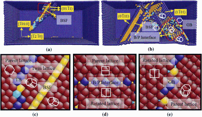
Fig. 2 Structures of initial plasticity under tension at θ = 0° under ε = 7.2% a, and ε = 7.3% b. Magnified atom configurations of initial defects: c T1 and BSF, d basal/prismatic (B/P) interface between the parent lattice and the rotated lattice, and e grain boundary (GB) between the parent lattice and rotated lattice

3.2 Details of Initial Plastic Deformation under Tension

(1)θ = 0° : Fig. 2 shows the microstructural evolution of the [ 1̅2 1̅0]-oriented nano-pillar under a-axis tension. Snapshots in Fig. 2a, b are the deformation modes when the strains are 7.2% and 7.3%, respectively. The atoms on perfect hcp lattice are made invisible, while the stacking fault and twin boundary are shown in yellow and blue. When the tension strain is 7.2%, it is found that the {10 1̅1} twin nucleates at the free surface (Fig. 2a). The similar deformation mechanism at a-axis tension was also observed and identified by Li et al. [27]. Subsequently, due to the lattice rotation caused by {10 1̅1} twinning, the basal stacking fault (BSF) forms in the twin region (Fig. 2a, c). When the tension strain is up to 7.3%, crystallographic reorientation appears in the sample which is highlighted in the red frame (Fig. 2b). Two semi-coherent basal/prismatic (B/P) interfaces are observed in two opposite boundaries of the crystallographic reorientation region, which are connected to the rotated crystal with the parent lattice. Moreover, in the rest side of the crystallographic reorientation region, typical grain boundaries (GB) exist between the parent and the rotated lattice. Figure 2d, e displays the amplified structures of the B/P interface and the grain boundary, respectively. In order to make the observation clear, the interface is plotted perpendicular to the paper in the magnified view.

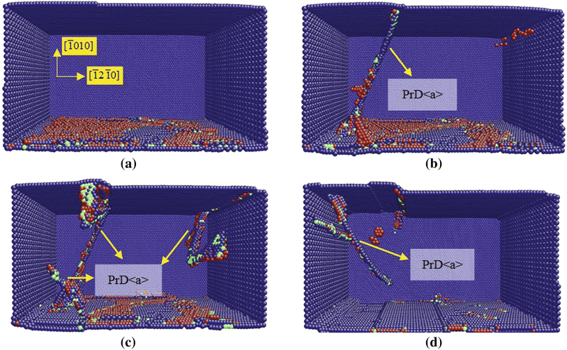
(2)θ = 20° : The plastic deformation occurs when the strain is up to 6.1% at θ = 20° , and a prismatic < a> dislocation loop nucleates at the free surface preferentially, as shown in Fig. 3a. Subsequently, Fig. 3b reveals that {10 1̅1} twins, stacking faults and crystallographic reorientations appear in the next 2000 steps relaxation with the strain increases to 6.16%. The stacking fault planes are presented in yellow. The twin boundary and the rotated crystal interface which are similar to the structures in Fig. 2b are also marked. Comparing the results of θ = 0° and θ = 20° , it is found that the initial plastic deformation is different. The initial plastic defect is the {10 1̅1} twinning for θ = 0° and the prismatic < a> dislocation forθ = 20° . However, the subsequent plastic deformation mechanisms are almost the same, which include with {10 1̅1} twins, basal stacking faults and crystal reorientation. The B/P interfaces are also observed accompanying the crystal reorientation for the case of θ = 20° .

Fig. 3 Structures of initial plasticity under tension at θ = 20° under ε = 6.1% a and ε = 6.16% b

(3)θ = 31.6° /45° : When θ is up to 31.6° and 45° , the Schmid factors of the basal (0001) [ 1̅2 1̅0] direction are 0.446 and 0.5, while those of the prismatic (1 1̅00)[11 2̅0] direction are 0.356 and 0.217. To some extent, the basal slip is easier to occur than the prismatic slip due to its higher Schmid factor. As shown in Fig. 4, the circle column model shows a leading dislocation in basal plane is prior to nucleate from the surface at the strain of 5.5% (Fig. 4a) when θ is 45° . After that, a trailing dislocation follows to fulfill the basal < a> dislocation in the next 3000 steps relaxation (Fig. 4b). When the strain increases to 5.68%, a full prismatic < a> dislocation appears as marked in Fig. 4c. However, the reverse result is observed at θ = 31.6° that a full prismatic < a> dislocation nucleates firstly, followed by the basal < a> dislocation. For the square column sample, the full prismatic < a> dislocation always appears firstly (Fig. 5a), and then the basal < a> dislocation follows (Fig. 5b). Moreover, it is observed that the basal slip can follow the prismatic one more quickly with increasing θ , which may contribute to the surface effect that plays an important role in the difference between the circle and square models. We noticed that all the basal < a> dislocations are fulfilled by two successive partial dislocations. After the leading partial dislocation 1/6 (0001)[ 1̅2 1̅0], a relative stable stacking fault forms and then the trailing dislocation follows. For the case of the prismatic < a> dislocation, there is no stable stacking fault configuration after the leading dislocation. We found out that the trailing partial dislocation nucleates immediately and catches up with the leading one, so that a perfect prismatic dislocation will be formed without any extensive stacking fault generated.

Fig. 4 Initial deformation mechanism of the circle column viewed along the loading y direction at θ = 45° with the strains of 5.5% a, 5.59% b, and 5.68% c

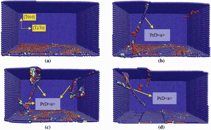
Fig. 5 Initial deformation mechanism of the square column under tension at θ = 31.6° . a The structure with prior defect of prismatic < a> dislocation. b The structure with the following defect of basal < a> dislocation

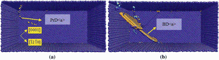
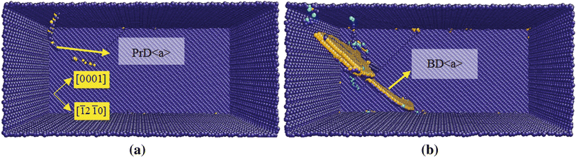
(4)θ = 58.4° /75° /80° : Fig. 6 shows the initial plastic deformation of the square column sample at θ = 58.4° . When the applied strain is up to 5.2%, a shear band (SB) appears at the free surface caused by the { 1̅2 1̅1} pyramidal slip (Fig. 6a). Meanwhile, the stress drops to almost zero after the { 1̅2 1̅1} pyramidal slip occurs. With the increase in the strain, the SB extends across the sample accompanying with the movement of the { 1̅2 1̅1} interfaces (Fig. 6b, c). The SB will grow continually and then expands until the second reorientation band appears at a large strain. No other types of defects can be observed in such condition. Figure 6d displays a magnified view of the SB in black square line region. The colorful atoms are marked according to the coordinates along [ 1̅010] direction. It is clearly shown that the atomic configuration of SB region is not mirror symmetrical to that of the original lattice, although the SB region is still in perfect hcp structures. This result provides a solid evidence to prove that the deformation in this region does not twin. The reorientation occurs in this pyramidal shear band with the rotation angle of 34° , just as the misorientation angle of the {11 2̅1} twin. Therefore, this deformation was usually defined as {11 2̅1} twin in previous works [43, 44, 45].

Fig. 6 Initial deformation mechanism of square column under tension at θ = 58.4° with the strains of 5.2% a, b and 5.3% c. d Magnified figure of the shear band

For the square column sample, the deformation mechanisms at θ = 75° and θ = 80° are similar as that of 58.4° , so they are not shown in detail here. However, for the cylindrical column sample, the results show a slight difference. When θ = 58.4° , the basal < a> dislocation is prior to nucleate at the surface which is marked as light blue in Fig. 7a. And the pyramidal shear band, which is similar to the structure in Fig. 6d, propagates with the increase in the strain (Fig. 7b). With the increase in θ , the basal slip is restrained. Whenθ is up to 75° , the pyramidal shear band appears prior to the basal slip. Further increasing θ to 80° , the pyramidal shear band is an only way for deformation, which is exactly consistent with the result of the square column. We suppose that the appearance of the basal < a> dislocation ahead of the pyramidal shear band is caused by the existence of the uneven surface for the cylindrical column models.

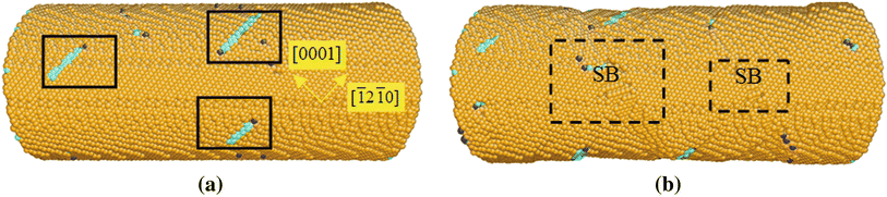
Fig. 7 Initial deformation mechanism of circle column under tension at θ = 58.4° . a The prior defect of basal < a> dislocation. b The following defect of shear band

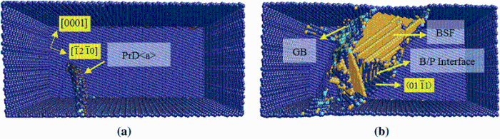
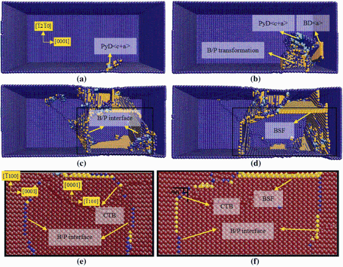
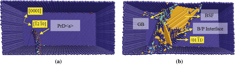
(5) θ = 90° : Under tensile loading along c-axis, in addition to pyramidal dislocations, the basal/prismatic (B/P) transformation is the main plastic deformation mechanism. Figure 8a-d show that the pyramidal dislocation is prior to occur in the stage of plastic flow, and soon the B/P transformation and the basal slip follow. Figure 8e and f exhibits the magnified atom configurations of B/P transformation. The B/P interface will run through the cross section and extend toward the terminal of crystal model by shuffling. Meanwhile, the basal stacking fault (BSF) also appears (Fig. 8d). The {10 1̅2} coherent twin boundary (CTB) connecting the B/P interface is observed in Fig. 8e, f. Our simulation result is consistent with the study of Liu et al. [31, 32] that the B/P transformation is a different mechanism compared with the twinning.

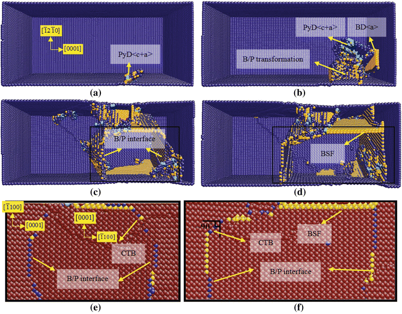
Fig. 8 Initial deformation mechanism of the square column under tension at θ = 90° . a Pyramidal dislocation nucleates at the free surface at the strain of 8.1%. B/P transformation and BSF formation at strain of 8.2% b, 8.7% c and 9.5% d, respectively. e, f Magnified atom configurations of B/P transformation

According to previous experimental and simulated results [6, 26, 46, 47], the {10 1̅2} twins and pyramidal slips are main plastic deformation mechanisms under c-axis tension. However, only the B/P interface is observed in our simulation when the loading is applied under c-axis tension. Actually, Wang et al. have also presented similar results to investigate that the growth mechanism of B/P interface and the nucleation of CTB in magnesium single-crystal system [48]. Theoretically, the {10 1̅2} twinning and the B/P transformation can accommodate the tensile strain along the c-axis due to the crystal rotation of about 90° [29, 30]. However, both the interface structures and transformation mechanisms are totally different. For the case of B/P transformation, the migration occurs at the interface between the semi-coherent basal and the prismatic plane which is dominated by local rearrangements of atoms [31]. For the case of {10 1̅2} twinning, the interface between the parent crystal and the twin is {10 1̅2} plane, which can be generally described by the mechanisms of twinning dislocation [49, 50] and the shuffling [51, 52, 53]. Yu et al. [54] revealed that the stress which was required for deformation twinning increased drastically with decreasing sample size. Therefore, the twinning dislocations may not be activated in the nano-pillar samples. Nevertheless, the sample size in our simulation system is at the nanoscale, implying that there is a competition between the {10 1̅2} twinning and the B/P transformation under c-axis tension. We have carefully examined the simulation system of c-axis tension for magnesium single crystal in our previous study [26]. We concluded that besides the observed {10 1̅2} twin, the B/P interface also exists at the boundary of the twin region (shown in Figs. 2, 3in Ref. [26]). From the simulation results, it is seen that CTB appears under c-axis tension and always connects to the B/P interface. Moreover, the B/P interface has also been observed when the tension loading is applied near the a-axis, which is accompanied with the crystal reorientation.

3.3 Details of Initial Plastic Deformation Under Compression

(1) θ = 0° : Fig. 9 shows snapshots of the deformation process of the [ 1̅2 1̅0]-oriented nano-pillar under a-axis compression. As marked by the red atoms in Fig. 9a, the surface relaxation makes the atoms on one of the prismatic planes active at strain of 6.7%. With increasing strain, the prismatic < a> dislocation nucleates on (01 1̅0) plane and then propagates immediately in the pillar (Fig. 9b). After that, the prismatic < a> dislocation on (11¯ 00)(11¯ 00) plane follows and runs out of the pillar rapidly (Fig. 9c). As the strain increases, the prismatic < a> dislocations nucleate successively on (01 1̅0) and (1 1̅00) planes, then propagate to the free surface and annihilate there, resulting in the appearance of steps at the surface (Fig. 9c and d). Due to the higher Schmid factor of 0.433, it is not surprising that the prismatic slips are main mechanism of plastic deformation for [ 1̅2 1̅0] compression. Furthermore, no twins appear at the initial plastic stage, which is different from the experimental result of micro-compression in magnesium [25].

Fig. 9 Microstructure evolutions of the [ 1̅2 1̅0]-oriented square pillar under compression with the strains of ε = 5%a, ε = 6.7% b, ε = 6.8% c and ε = 6.9% d

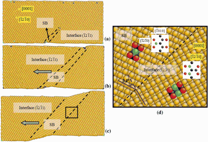
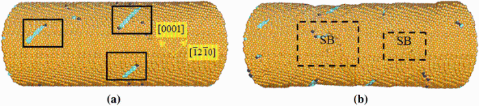
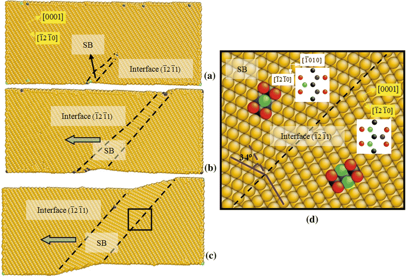
(2) θ = 10° /15° /20° : The deformation mechanisms under compression at θ = 10° -20° are consistent with those at θ = 58.4° under tension that the main deformation was dominated by SB. Taking the compression simulation of θ = 20° with the strain up to 4.8% as an example, the SB occurs with a rotation of 34° due to { 1̅2 1̅1} pyramidal slips. As the strain increases, the SB grows with the movement of the interface and the rotated crystal expands until the second reorientation occurs.

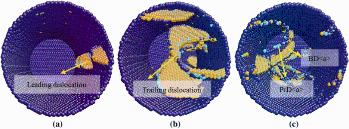
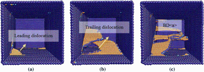
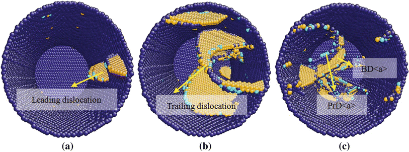
(3)θ = 31.6° /45° /58.4° : As expected, the basal slip is main contribution to the strain accommodation due to the high Schmid factor and low critical resolved shear stress (CRSS) in the θ range from 20° to 75° . The slip plane is clearly presented by the yellow atoms in Fig. 10. At the plastic stage, the leading partial dislocation in basal plane starts and the stacking fault follows, as shown in Fig. 10a. Then, the trailing partial basal dislocation appears in Fig. 10b. With the increase in the strain, more basal < a> dislocations appear as shown in Fig. 10c.

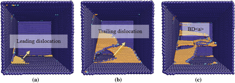
Fig. 10 Microstructure evolutions of the square column under compression at θ = 31.6°

(4) θ = 75° /80° /90° : When compression loading is applied near or along the c-axis, the main mechanism of plastic deformation is pyramidal and subsequent basal slips which are coincident with the previous simulation results of c-axis compression presented by Guo et al. [30]. Their results also revealed that a leading partial pyramidal dislocation nucleated at the free surface, and then, a trailing partial pyramidal dislocation followed successively, which leads to a perfect {10 1̅1} pyramidal I dislocation loop appear. The dissociation processes of the pyramidal I < c+a> dislocation on {10 1̅1} plane in magnesium have also been presented in previous works [55, 56]. At the high strain condition, the basal slip is subsequently observed due to the complicated stress condition caused by pyramidal dislocation nucleation and movement.

3.4 Initial Plasticity of Nano-pillar with Different Orientations as Predicted by Sun’ s EAM Potential

In order to comprehensively evaluate deformation mechanism for magnesium single crystal, more extensive simulations and comparisons are imperative by using the empirical potentials. Therefore, Sun’ s EAM potential [35] was introduced in our calculation for the same simulation models. Compared with the incipient deformation modes which were simulated by Liu’ s EAM, most of the simulation results calculated by Sun’ s EAM potential are similar. Only a small portion of results have shown a slight difference, which may be attributed that the prismatic < a> dislocation is not easy to nucleate, while the basal < a> dislocation behaves more actively. For instance, no prismatic < a> dislocations appear in tension simulations when θ is 15° -20° , and only {10 1̅1} twins, stacking faults and crystallographic reorientations are observed. When θ is at the range from 31.6° to 58.4° , the basal slip is the only way for deformation. For θ of 58.4° to 75° , the basal slips are prior to occur, followed by the SB.

3.5 Comparison of Simulation and Experimental Results

To make our simulation results more convincible and reliable, several published experimental results of magnesium as the comparison to our simulation have been surveyed in following. For the case of experimental results, uniaxial micro-compressions of magnesium single crystal along [0001], [2 1̅1̅2] and [11 2̅0] compression axes were examined by Kim et al. [25]. Both Kim’ s experimental results and our molecular dynamic simulations consistently have shown that the basal slip is the dominated deformation mechanism in [2 1̅1̅2]-oriented compression. Ye et al. also verified that the basal slip is active in the sample when the basal plane was at an angle of 30° with reference to the loading axis [22]. For the case of the [11 2̅0]-oriented (a-axis) compression experiment [25], it was revealed that the tension twinning happens and the prismatic < a> dislocation nucleates in the untwined region. However, only the prismatic < a> dislocations contribute to the initial plastic deformation, and no tension twins participate in our a-axis compression simulations. Dynamic and quasi-static compressive experiments along the direction about 10° away from the [0001] c-axis were carried out by Li et al., which showed that the prismatic and {11 2̅2} pyramidal II dislocation operations happened in the samples under the quasi-static and dynamic loadings, while the tension twinning and tension-compression double twinnings also happened in the sample under quasi-static loading [57]. For the case of the [0001][0001] c-axis micro-compression experiments, Lilleodden et al. discovered the activation and multiplication of < c+a> dislocations on the 6 equivalent pyramidal II slip systems and no twins are found [19]. In our simulations, although no twins are observed, pyramidal I slip is regarded as the dominated deformation mechanism which is different from the experimental result that pyramidal II slip dominates. Recently, a large-scale molecular dynamics simulation by Tang et al. presented an explanation for this discrepancy between the experiments and simulations [28]. It revealed that the formation of < c+a> dislocations during c-axis loading occurred by sequential nucleations of leading and trailing partial dislocations on the pyramidal I planes, but then subsequent transition of pyramidal I slip to pyramidal II planes was achieved. Thus, only the pyramidal II slips can be observed in the experiments. To some extent, it is not strange that there are discrepancies between the simulated results and experiments. Actually, most experiments are applied for polycrystalline or bulk single-crystal materials. Even in micro-compression experiments of magnesium single crystals, pre-existing defects and material inhomogeneity are considered to influence the mechanism of the initial deformation, which is different from the condition of our simulation of pure magnesium single crystals. Moreover, the conditions of initial deformation are well defined in our simulations, which was difficult to be investigated in practical experiments. Hence, the discrepancy between the simulations and the experiments should be observed.

Based on the simulated and experimental results, it can be concluded that when the loading is applied at the direction of around 45° from c-axis or a-axis, the basal dislocation dominates the initial plasticity due to the high Schmid factor and low critical resolved shear stress (CRSS). In our simulations, the prismatic slip is also observed under the tension along the loading axis of about 45° which may be caused by the free surface and the nano-size effect. When the loading is applied near c-axis or a-axis, the basal slip is restricted; thus, pyramidal slips, twinning, crystal reorientation and B/P transformation occur. In the a-axis compression, the prismatic slip dominates the initial plastic deformation because some prismatic planes of magnesium single crystal are in the preferred slip directions, which are not perpendicular or parallel to the loading direction. Besides, it is noticed that the twinning, crystal reorientation and basal/prismatic transformation only appear in the crystal model loaded along or near the a-axis or c-axis. It means that the twinning, crystal reorientation and basal/prismatic transformation are not easy to active compared with the basal and prismatic slips. Thus, they can only occur when the basal and prismatic slips are restricted.

3.6 Orientation Effect on the Yield Strength

It is well known that the initial deformation mechanism has a predominant influence on the maximum yield stress (σ max), which may vary with different crystallographic orientations and loadings. In Table 2, σ maxand the initial deformation mechanisms with different orientations under tension and compression are listed. In the tension simulations, the lowest σ max values (about 1.6 GPa) correspond to θ = 0° -10° , while the simultaneous initial defects of {10 1̅1} twin and the basal stacking fault occur. When θ = 15° -45° , the values of σ max are in the range of 1.6-2.5 GPa, and the initial defects are the prismatic < a> dislocations. With the increase in θ , SB is the primary deformation mechanism and the corresponding values of σ max are much higher (about 2.3-3.3 GPa). When the loading direction is c-axis, the prior defect of the pyramidal < c+a> dislocation makes σ max become the highest (4.01 GPa). σ max, which are predominated by the initial deformation mechanism of the basal < a> dislocation and SB, respectively, is in the range of 1.7-1.9 GPa and 1.9-2.1 GPa in the compression simulations. When θ = 75° -90° , σ max is much higher because the pyramidal < c+a> dislocations are the prior deformation defects. Interestingly, for the case of a-axis compression, although the initial defect is the prismatic < a> dislocation, the value of σ max is still much high.

Table 2 Initial defects and maximum yield stresses (σ max) with different orientations under the tension and compression

Furthermore, due to different plastic deformation mechanisms under the tension and compression, the maximum tension yield stress (σ max-t) and compression yield stress (σ max-c) are different. We can see that σ max-t is lower than σ max-c when θ is less than 31.6° , and σ max-t exceeds σ max-c when θ is in the range of 31.6° -58.4° . Therefore, the values of the tension and compression strengths strongly depend on the loading orientation. Therefore, it is well to say that σ max-t and σ max-c near c-axis and σ max-c at a-axis are much bigger than the loading in other directions.

4 Conclusions

Molecular dynamics simulations were used to study the tension and compression behaviors of magnesium single crystals with different orientations. For ten different orientations with the angles ranging from 0° to 90° , different plastic deformation mechanisms are observed. For both tension and compression, when the loading is applied at the directions of around 45° from c-axis or a-axis, the basal dislocation dominates the initial plasticity due to the high Schmid factor and low CRSS. When the loading is applied near c-axis or a-axis, the basal slip is restricted; thus, the pyramidal slips, twinning, crystal reorientation and B/P transformation occur. Both B/P interface and CTB appear under c-axis tension, while the CTB always connect the B/P interface. Besides, the B/P interfaces are also observed under a-axis tension accompanying the crystal reorientation. In compression simulations with different orientations, the basal, prismatic and pyramidal slips dominate the plastic deformation. No twins participate in the deformation, although the twin-like shear bands caused by the {11 21̅1} slips are observed. Furthermore, the deformation mechanism affects the yield strength. The values of the σ max-t and the σ max-c have a relationship with the sample orientation. Particularly, σ max-t and σ max-c near c-axis and σ max-c at a-axis are much bigger than loading in other directions.

Acknowledgments

This work was financially supported by the National Natural Science Foundation of China (No. 11372032) and The Open Project of Key Laboratory of Computational Physics in China.

The authors have declared that no competing interests exist.

Reference
[1] S. Xu, Y. F. Guo, A. H. W. Ngan, Int. J. Plast 43, 116 (2013) [Cite with in:3]
[2] A. H. W. Ngan, Scr. Mater. 65, 978(2011) [Cite with in:1]
[3] J. Kim, R. Golle, H. Hoffmann, Mater. Sci. Eng. , A 527, 7220 (2010) [Cite with in:1]
[4] X. Y. Li, W. Yang, J. Nanomater. 2009, 245941(2009) [Cite with in:2]
[5] T. Al-Samman, K. D. Molodov, D. A. Molodov, G. Gottstein, S. Suwas, Acta Mater. 60, 537(2012) [Cite with in:1]
[6] H. G. Qi, Y. F. Guo, X. Z. Tang, S. Xu, Acta Metall. Sin. (Engl. Lett. ) 24, 487(2011) [Cite with in:3]
[7] A. Cao, E. Ma, Acta Mater. 56, 4816(2008) [Cite with in:1]
[8] Y. Chun, C. H. J. Davies, Mater. Sci. Eng. , A 528, 5713 (2011) [Cite with in:1]
[9] Y. Fan, Y. N. Osetsky, S. Yip, B. Yildiz, Phys. Rev. Lett. 109, 135503(2012) [Cite with in:1]
[10] T. Zhu, J. Li, A. Samanta, A. Leach, K. Gall, Phys. Rev. Lett. 100, 025502(2008) [Cite with in:1]
[11] X. Z. Lin, D. L. Chen, Mater. Sci. Eng. , A 496, 106 (2008) [Cite with in:1]
[12] J. Y. Kim, D. Jang, J. R. Greer, Int. J. Plast 28, 46 (2012) [Cite with in:2]
[13] D. L. Yin, J. T. Wang, J. Q. Liu, X. Zhao, J. Alloy. Compd. 478, 789(2009) [Cite with in:1]
[14] X. Y. Lou, M. Li, R. K. Boger, S. R. Agnew, R. H. Wagoner, Int. J. Plast 23, 44 (2007) [Cite with in:1]
[15] M. Battaini, E. V. Pereloma, C. H. J. Davies, Metall. Mater. Trans. A 38, 276 (2006) [Cite with in:2]
[16] D. W. Brown, S. R. Agnew, M. A. M. Bourke, T. M. Holden, S. C. Vogel, C. N. Tomé, Mater. Sci. Eng. , A399, 1(2005) [Cite with in:1]
[17] E. W. Kelley, W. F. Hosford, Trans. Metall. Soc. AIME 242, 5 (1968) [Cite with in:3]
[18] B. C. Wonsiewicz, W. A. Backofen, Trans. Metall. Soc. AIME 239, 1422 (1967) [Cite with in:1]
[19] E. Lilleodden, Scr. Mater. 62, 532(2010) [Cite with in:2]
[20] C. M. Byer, K. T. Ramesh, Acta Mater. 61, 3808(2013) [Cite with in:2]
[21] A. Chapuis, Mater. Sci. Eng. , A 590, 401 (2014) [Cite with in:1]
[22] J. Ye, R. K. Mishra, A. K. Sachdev, A. M. Minor, Scr. Mater. 64, 292(2011) [Cite with in:3]
[23] E. W. Kelley, W. F. Hosford, Trans. Metall. Soc. AIME 242, 654 (1968) [Cite with in:2]
[24] S. Graff, W. Brocks, D. Steglich, Int. J. Plast 23, 1957 (2007) [Cite with in:1]
[25] G. S. Kim, Small Volume Investigation of Slip and Twinning in Magnesium Single Crystals, Seoul National University, 2011 [Cite with in:4]
[26] Y. F. Guo, Y. S. Wang, H. G. Qi, D. Steglich, Acta Metall. Sin. (Engl. Lett. ) 23, 370(2010) [Cite with in:4]
[27] B. Li, E. Ma, Acta Mater. 57, 1734(2009) [Cite with in:3]
[28] Y. Tang, J. A. El-Awady, Acta Mater. 71, 319(2014) [Cite with in:2]
[29] Y. F. Guo, X. Z. Tang, Y. S. Wang, Z. D. Wang, S. Yip, Acta Metall. Sin. (Engl. Lett. ) 26, 75(2013) [Cite with in:2]
[30] Y. F. Guo, S. Xu, X. Z. Tang, Y. S. Wang, S. Yip, J. Appl. Phys. 115, 224902(2014) [Cite with in:3]
[31] B. Y. Liu, J. Wang, B. Li, L. Lu, X. Y. Zhang, Z. W. Shan, J. Li, C. L. Jia, J. Sun, E. Ma, Nat. Commun. 5, 3297(2014) [Cite with in:3]
[32] B. Y. Liu, L. Wan, J. Wang, E. Ma, Z. W. Shan, Scr. Mater. 100, 86(2015) [Cite with in:2]
[33] S. Plimpton, Comput. Phys. 117, 1(1995) [Cite with in:1]
[34] X. Y. Liu, P. P. Ohotnicky, J. B. Adams, C. L. Rohrer, Surf. Sci. 373, 357(1997) [Cite with in:1]
[35] D. Y. Sun, M. I. Mendelev, C. A. Becker, K. Kudin, T. Haxhimali, M. Asta, J. J. Hoyt, A. Karma, D. J. Srolovitz, Phys. Rev. B 73, 024116 (2006) [Cite with in:2]
[36] J. A. Yasi, T. Nogaret, D. R. Trinkle, Y. Qi, L. G. Hector Jr, W. A. Curtin, Model. Simul. Mater. Sci. Eng. 17, 055012(2009) [Cite with in:1]
[37] T. Nogaret, W. A. Curtin, J. A. Yasi, L. G. Hector Jr, D. R. Trinkle, Acta Mater. 58, 4332(2010) [Cite with in:1]
[38] T. M. Reed, K. E. Gubbins, Applied Statistical Mechanics (McCraw-Hill, New York, 1973) [Cite with in:1]
[39] D. A. McQuarrie, Statistical Mechanics (Harper and Row, New York, 1976) [Cite with in:1]
[40] H. Goldstein, Classical Mechanics (Addison-Wesley, Massachusetts, 1980) [Cite with in:1]
[41] J. Li, Model. Simul. Mater. Sci. Eng. 11, 173(2003) [Cite with in:1]
[42] G. J. Ackland , A. P. Jones, Phys. Rev. B 73, 054104 (2006) [Cite with in:1]
[43] N. J. Lane, S. I. Simak, A. S. Mikhaylushkin, I. A. Abrikosov, L. Hultman, M. W. Barsoum, Phys. Rev. B 84, 184101 (2011) [Cite with in:1]
[44] A. Serra, D. J. Bacon, R. C. Pond, Metall. Mater. Trans. A 33, 809 (2002) [Cite with in:1]
[45] Y. Minonishi, S. Ishioka, M. Koiwa, S. Mobozumi, Phys. Status Solidi A 71, 253 (1982) [Cite with in:1]
[46] M. D. Nave, M. R. Barnett, Scr. Mater. 51, 881(2004) [Cite with in:1]
[47] J. H. Park, H. L. Kim, J. E. Jung, Y. W. Chang, Met. Mater. Int. 19, 389(2013) [Cite with in:1]
[48] J. Wang, S. K. Yadav, J. P. Hirth, C. N. Tomé, I. J. Beyerlein, Mater. Res. Lett. 1, 126(2013) [Cite with in:1]
[49] A. Serra, D. J. Bacon, Philos. Mag. A 73, 333 (1996) [Cite with in:1]
[50] A. Serra, D. J. Bacon, P. C. Pond, Phys. Rev. Lett. 104, 029603(2010) [Cite with in:1]
[51] B. Li, E. Ma, Phys. Rev. Lett. 103, 035503(2009) [Cite with in:1]
[52] B. Li, E. Ma, Phys. Rev. Lett. 104, 029604(2010) [Cite with in:1]
[53] B. Li, X. Y. Zhang, Scr. Mater. 71, 45(2014) [Cite with in:1]
[54] Q. Yu, Z. W. Shan, J. Li, X. Huang, L. Xiao, J. Sun, E. Ma, Nature 463, 335 (2010) [Cite with in:1]
[55] B. Li, E. Ma, Philos. Mag. 89, 1223(2009) [Cite with in:1]
[56] Q. Zu, Y. F. Guo, X. Z. Tang, Acta Metall. Sin. (Engl. Lett. ) 28, 876(2015) [Cite with in:1]
[57] Q. Z. Li, Mater. Sci. Eng. , A 568, 96 (2013) [Cite with in:1]