
Effect of Active Gas on Weld Shape and Microstructure of Advanced A-TIG-Welded Stainless Steel
[Reza Nakhaei1  , Alireza Khodabandeh
1 , Hamidreza Najafi1 ]
, Alireza Khodabandeh|
|


Advanced A-TIG method was conducted to increase the weld penetration and compared with the conventional TIG welding process. A two-pipeline setup was designed to apply Ar + CO2 mixed gas as the outer layer, while pure argon was applied as the inner layer to prevent any consumption of the tungsten electrode. The results indicate that the presence of active gas in the molten pool led to the change in the temperature coefficient of surface tension so that the Marangoni convection turns inward and forms a deep weld zone. The increase in gas flow rate causes a decrease in the weld efficiency which is attributed to the increase in oxygen content in the weld pool and the formation of a thicker oxide layer on the weld surface. Moreover, the stir and the temperature fluctuation, led by double shielding gas, create more homogeneous nucleation sites in the molten pool so that a fine grain microstructure was obtained.
Due to its good weld quality, stable heat source and low equipment costs, tungsten inert gas (TIG) welding has become one of the most widely accepted choices of welding techniques for stainless steels. However, in comparison with other conventional arc welding methods, the shallow joint penetration and low deposition rate in a single pass restrict the TIG welding of thick plates [1, 2, 3, 4]. Accordingly, recent studies have been focused on the various solutions to improve the weld penetration by modifying equipment and adding active elements into the weld pool [5, 6, 7, 8, 9, 10, 11]. For example, Manikandan et al. [5] reported that pulsed current GTAW produced narrower welds with smaller HAZ and finer grain structure. Cunha and Enrique [12] showed that U-TIG welding method increased the weld penetration compared with conventional TIG welding process by adding the ultrasonic system on the welding apparatus. Zhang et al. [13] proposed the technology of hybrid laser-TIG welding on the thick plates of structural steels. This technique increased the fusion zone by employing laser near the welding torch. The active flux TIG (A-TIG) welding is another way to increase the weld depth. A satisfactory weld shape with deep penetration would be acquired by preplacing the oxide fluxes, such as SiO2 or TiO2, on the surface of workpiece in the A-TIG [14]. However, stability and quantity of the flux have a great influence on the quality of the weld that is not suitable to industrial automation [15]. Some researchers found that even a small addition of an active gas such as O2, CO2 and SO2 into the shielding gas leads to Marangoni convection change in the weld pool from outward to inward so as to improve the weld penetration [16, 17]. However, the results showed that the addition of mentioned gases into the inert shielded gas inevitably causes heavy oxidation on the electrode tip shortening the electrode application life. To solve this problem, a double-shielded method (AA-TIG) has been proposed to prevent any consumption of the tungsten electrode [18, 19, 20, 21]. In this case, the inner shielding gas (pure inert gas) protects the tungsten electrode, while the outer mixed gas, containing a small amount of oxygen or carbon dioxide, is applied to dissolve in the weld pool so as to change Marangoni convection and the weld pool shape.
The active gas concentration, welding current and gas flow rate would be the most important parameters in the advanced A-TIG method. Hence, effects of these parameters on the welding efficiency and the fusion zone profile were studied under both advanced A-TIG and conventional TIG processes.
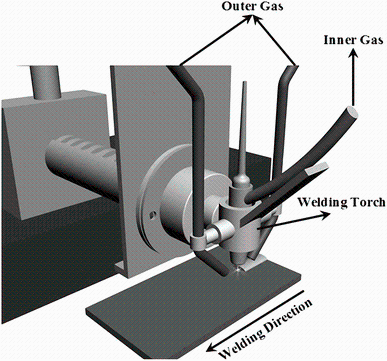
The SUS 304L samples with dimensions of 200 mm × 80 mm × 6 mm were applied for the bead-on-plate welding experiments. The composition of the base alloy is presented in Table 1. At first, the samples were prepared by conventional grinding techniques up to 200 grits and then cleaned with alcohol to remove contamination from the workpiece surface. A specific torch was designed to weld the samples using double-shielded gases (see Fig. 1). The steel samples were welded by the advanced A-TIG process under the double shielding gas with pure argon as the inner shielding gas, while the outer gas was mixed Ar-CO2. The oxygen content in the fusion zone was changed by adjusting the active gas (CO2) concentration in the outer shielding gas at three levels of 0, 0.5 and 2 vol%. Pure argon was also applied as the shielding gas in the conventional TIG welding. The welding parameters for the samples are given in Table 2.
| Table 1 Chemical composition of base alloy SS304L (in wt%) |
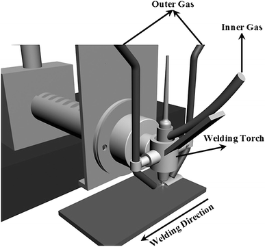 | Fig. 1 Schematic diagram of advanced A-TIG welding process using a specific torch |
| Table 2 Welding parameters for different samples |
The welded samples were transversely cut and polished to 1 µ m diamond finish for metallographic observations. The chemical etchants for stainless steel were marble (10 g CuSO4, 50 mL HCl and 50 mL distilled water) and glyceregia (15 mL HCl, 10 mL HNO3, 10 mL acetic acid, two drops glycerin and distilled water) reagents [22]. Microstructural examination of the joints was performed by optical microscopy (OM) and scanning electron microscopy (SEM) equipped with energy-dispersive spectroscopy (EDS). The level of ferrite was measured by a microstructural image processor. Mitutoyo HM tester with the load of 0.98 N was also employed for microhardness measurements.
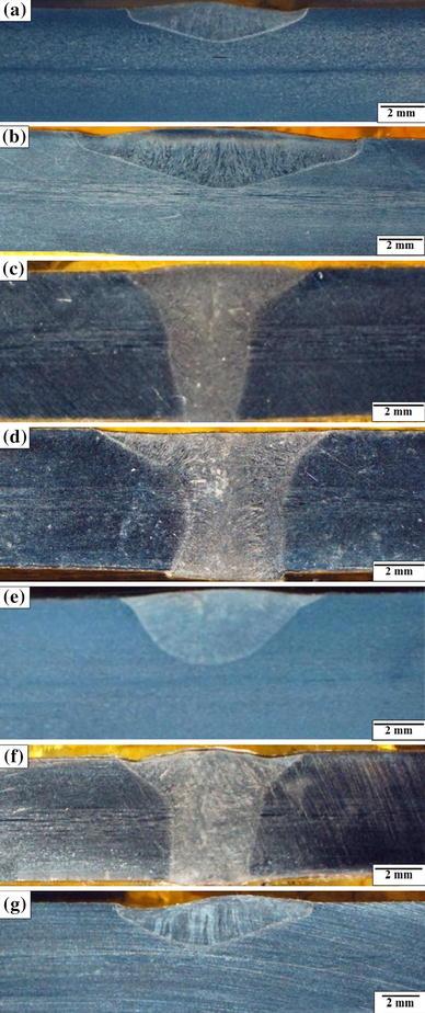
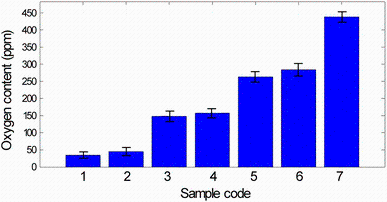
Typical weld cross sections and dimensions of fusion zone profiles are illustrated in Fig. 2 and Table 3, respectively. It is clear that the active gas (CO2) can remarkably increase the weld penetration and reduce the weld width in a certain range of welding parameters. The maximum weld penetration of 2.5 mm is estimated for conventional TIG welding, whereas the narrow and deep weld pools up to 6 mm are formed by advanced A-TIG process. It is suggested that the forces of Lorenz, Buoyancy, and Marangoni and arc pressure are responsible for the fluid flow in the weld pool. In the meantime, the Marangoni convection, induced by the surface tension gradient on the weld pool surface, plays a vital role to form a deep weld zone [19, 23]. Due to a large temperature gradient, existing from the center under the torch to the edges of the weld pool, a large surface tension gradient is created along the surface. Therefore, the fluid flows from the pool center to the edge and results in the formation of a wide weld pool. Taimatsu et al. [24] reported that the surface active elements such as oxygen can change the temperature coefficient of the surface tension for Fe alloys from negative to positive so that the Marangoni flow turns from edges to center and forms a narrow and deep pool. Considering oxygen content of the weld pools (see Fig. 3), it is found that the wide and shallow weld shape of conventional TIG process is caused by outward direction of surface tension, while the presence of higher oxygen content in advanced A-TIG leads to the change in Marangoni flow from outward to inward and the increase in the weld penetration.
 | Fig. 2 Geometric characteristics of weld metal: a sample 1; b sample 2; c sample 3; d sample 4; e sample 5; fsample 6; g sample 7 |
| Table 3 Weld dimensions of different samples (in mm) |
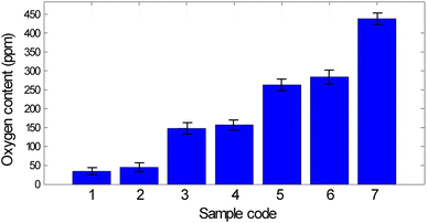 | Fig. 3 Oxygen content in the welded samples |
The effect of welding current on the weld shape is illustrated in Fig. 2. The welding current is at the two levels of 130 and 150 A. The weld depth/weld width (D/W) ratios of the samples, welded by the conventional TIG process with 130 and 150 A, are, respectively, 0.26 and 0.28. This indicates that the increase in welding current has a minor effect on D/W ratio, because the weld depth and the weld width concurrently increase. On the other hand, under the double shielding gas (Ar - 2 vol% CO2), the weld D/W ratio increases with the welding current which is quite different from the results acquired by the conventional TIG welding. The heat input and the weld D/W ratio will be altered by the change in welding current. In fact, the heat distribution of the arc can be the major factor influencing the weld penetration. The researchers reported that the enhancement of welding current led to the increase in magnitude of the heat intensity and subsequently temperature gradient on the weld pool surface [25]. Hence, the welding current has a straight relation with the Marangoni convection force on the weld pool surface. Moreover, Tanaka et al. [26] reported that the welding current can increase the strength of the electromagnetic convection in the liquid pool controlling the weld depth.
The gas flow rate is one of the most important parameters affecting the weld shape and the weld D/W ratio. As shown in Fig. 2f, g, with the increase in flow rate from 5 to 8 L/min, the weld efficiency decreases which is attributed to the enhancement of oxygen content in the weld pool and formation of a thicker oxide layer on the weld surface. Hence, the interface between the weld pool and shielding gas is limited and mechanism of weld depth increasing is reduced.
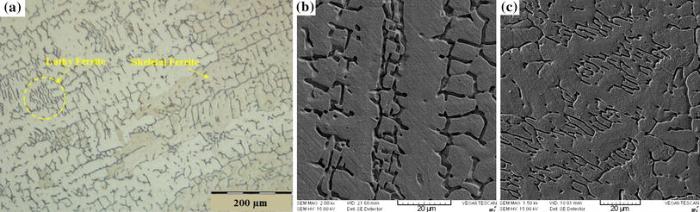
Figure 4 illustrates the microstructure of fusion zone profile made by conventional TIG process. The figure exhibits an austenitic, lathy and skeletal ferrite microstructure for the weld metal. These ferrite morphologies resulted from primary ferrite solidification which is followed by a subsequent solid-state transformation during cooling stage. During cooling of the weld zone, a considerable amount of ferrite is transformed into the austenite by a solid-state transformation process controlled by diffusion mechanism [27, 28]. It is believed that the ferrite morphologies are caused by a Cr-enriched Ni-depleted dendrite core which is formed during the primary stage of solidification. The presence of active gas (CO2) in the TIG welding method has a significant effect on the microstructure of fusion zone profile (see Fig. 5). The structure obtained by the TIG process has coarser columnar grain, while the dendrite arm spacing of the advanced A-TIG method is smaller and the weld metal has a more refined microstructure [29]. The stirring of molten pool via secondary shielding gas makes the structure more uniform and consequently leads to the less segregation in microstructure. The weld metal made by advanced A-TIG process has more homogeneous nucleation sites in the molten pool which is due to the stir and the temperature fluctuation so that the nucleation can occur over a wide range. Hereupon, the columnar grains in the molten pool stop growing whenever they contact each other, and consequently, the microstructure with fine grains would be obtained. Previous works indicated that the refinement of substructure can improve the mechanical properties of the welded joint [27, 29].
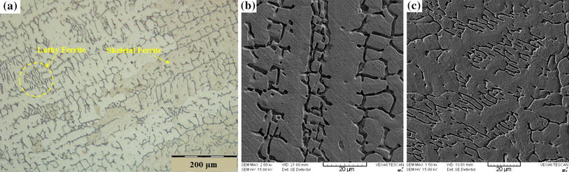 | Fig. 4 Microstructure of the fusion zone profile a lathy ferrite, b skeletal ferrite made by conventional TIG |
 | Fig. 5 Effect of active gas on the microstructure of weld metal: a sample 4, Ar + 0.5 vol% CO2. b Sample 6, Ar + 2.0 vol% CO2 |
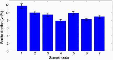
Ferrite content for the welded samples is given in Fig. 6. It can be observed that the levels of ferrite decrease with the increase in the welding current (means heat input). A reduction in the ferrite content can be led from the slower cooling rate when the welding current (heat input) increases. It is suggested that the cooling rate has a remarkable influence on the solidification of weld pool and the solid-state transformation of ferrite to austenite in the weld metal. Slower cooling rates hold longer the fusion zone profile in the transformation temperature range. Therefore, a substantial amount of the ferrite would be transformed to the austenite. Hence, a small percentage of the ferrite at room temperature would be attained. Elmer et al. [30] also indicated that the increase in cooling rate leads to a growth in the ferrite level as the solidification is in the primary ferrite phase mode. This can be due to the enhancement of original ferrite content from the solidified weld metal and a decrease in the ferrite to austenite solid-state transformation.
 | Fig. 6 Ferrite fraction in the weld metal of different samples |
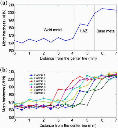
Figure 7 presents the microhardness profiles of the welded joints. Considering the general trend of the hardness profiles, it can be specified that the joint zone includes three distinct regions. The hardness value of 200-210 VHN introduces the base alloy, while the value near stainless steel falls to 180-190 VHN indicating the presence of HAZ. Adjacent to the HAZ, a drop in hardness value is observed which is due to the weld metal. The microhardness test shows that the hardness value tends to decrease with the increase in welding current and heat input. This tack can be attributed to two main reasons. Firstly, the reduction in ferrite content with the increase in heat input leads to an upward trend in the hardness value of weld metal. Secondly, the grain refinement of the weld metal by employing double shielding gas and increasing the welding current can be the key factor in the enhancement of hardness value of the fusion zone profile.
 | Fig. 7 a Schematic of different regions according microhardness measurement of the joint zone and bmicrohardness profiles of the welded samples |
(1) Advanced A-TIG welding method using a double shielding system with a slightly active gas (CO2) is applicable for any important construction made of stainless steel.
(2) The presence of the active gas in the molten pool leads to the change in the temperature coefficient of surface tension from negative to positive value so that the Marangoni convection turns inward and forms a deep and narrow weld pool. Under these conditions, the maximum weld penetration of 2.5 mm is obtained for conventional TIG welding, while the deep weld profiles up to 6 mm are formed by advanced A-TIG method.
(3) The increase in flow rate from 5 to 8 L/min leads to the reduction in the weld efficiency which is attributed to the increase in oxygen content in the weld pool and the formation of a thicker oxide layer on the weld surface.
(4) The weld metal made by advanced A-TIG process has more homogeneous nucleation sites in the molten pool. It is due to the stir and the temperature fluctuation led by the double shielding gas so that the nucleation can occur over a wide range, and subsequently, a fine grain microstructure will be obtained.
(5) Study on the microhardness test reveals that the reduction in the ferrite content with an increase in welding heat input can lead to a rise in the hardness value of weld metal.
The authors have declared that no competing interests exist.
| [1] |
|
| [2] |
|
| [3] |
|
| [4] |
|
| [5] |
|
| [6] |
|
| [7] |
|
| [8] |
|
| [9] |
|
| [10] |
|
| [11] |
|
| [12] |
|
| [13] |
|
| [14] |
|
| [15] |
|
| [16] |
|
| [17] |
|
| [18] |
|
| [19] |
|
| [20] |
|
| [21] |
|
| [22] |
|
| [23] |
|
| [24] |
|
| [25] |
|
| [26] |
|
| [27] |
|
| [28] |
|
| [29] |
|
| [30] |
|