Copyright reserved, Editorial board of Acta Metallurgica Sinica(English Letters)
Synthesis and Characterization of C-TiO2/FeTiO3 and CQD/C-TiO2/FeTiO3 Photocatalysts with Enhanced Photocatalytic Activities Under Sunlight Irradiation
1.Department of Chemistry, Osmania University, Hyderabad 500007, Telangana State, India
Abstract
Sunlight-driven C-TiO2/FeTiO3 composites were synthesized with different weight fractions of FeTiO3. The as-prepared samples were characterized by UV-Visible diffuse reflectance spectroscopy, Fourier transform infrared spectroscopy, X-ray diffraction analysis, transmission electron microscopy, scanning electron microscopy, energy-dispersive X-ray spectroscopy, and photoluminescence. Under sunlight irradiation, the C-TiO2/FeTiO3 photocatalysts degraded methyl orange (MO) efficiently and displayed much higher photocatalytic activity than that of pure FeTiO3 or carbon-doped titanium dioxide (C-TiO2), and the C-TiO2/FeTiO3 photocatalyst with 10 wt% of FeTiO3 exhibited the highest photocatalytic activity. The enhancement of photocatalytic activity was mainly ascribed to the formation of a heterojunction between C-TiO2 and FeTiO3, which facilitated the transfer and separation of photogenerated electron-hole pairs. The quenching effects of different scavengers demonstrated that the reactive superoxide radicals (·O2-) and hydroxyl radicals (·OH) played a major role in the MO degradation. The possible photocatalytic mechanism is discussed on the basis of the band structures of C-TiO2 and FeTiO3. To further enhance the photocatalytic efficiency, double-heterojunctioned CQD/C-TiO2/FeTiO3 composite was prepared by loading carbon quantum dots onto the C-TiO2/FeTiO3 surface.
Many organic pollutants have been found in different water resources. Dyes have been extensively used in different industries such as textile, paper, leather, plastics, pharmaceuticals, food, and cosmetic industries. A substantial amount of dyestuff is lost due to inefficiency of dying during the dyeing process, which poses a major problem to the environment [1, 2]. Photocatalysis is considered as a promising technique for the removal of dyestuffs from wastewater. Titanium dioxide (TiO2) is widely used as a photocatalyst because of its low cost, high activity, and nontoxicity. However, TiO2 is active only under UV light, but it cannot utilize the photons in the visible light due to its large band gap (Eg = 3.2 eV for anatase phase), which largely limits its application range [3]. Therefore, the usage of visible light active materials has recently drawn attention of the researchers. Sunlight is the most abundantly available, renewable, and clean source of energy, which is composed of ~46% of visible radiation and ~5% of UV radiation [4]. To efficiently use solar energy, many modification methods have been studied to extend the spectral response of TiO2 to the visible region, such as metal doping [5, 6], nonmetal doping [7, 8], semiconductor coupling [9, 10], and surface dye sensitization [11, 12]. Nonmetal doping, such as carbon [13] or nitrogen [14], has displayed promising results in shifting the light absorption of TiO2 into visible region. As far as visible light photocatalytic activity is concerned, C-doped TiO2 was found to be more active than N-doped TiO2 [15, 16, 17]. However, nonmetal doping intrinsically brings the serious problem of massive charge carrier recombination, which largely limits the visible light photocatalytic activity of nonmetal-doped TiO2. From the viewpoint of practical application, higher photocatalytic reaction efficiency is required since the photocatalytic efficiency of nonmetal-doped TiO2 under visible light is still low [17, 18]. Recently, coupling of semiconductor with other semiconductor to form a heterojunction structure has been widely used to enhance the photocatalytic performance of photocatalysts [19, 20, 21]. Therefore, modification of C-TiO2 with other semiconductors can be considered as an effective approach to promote the visible light activity by minimizing charge carrier recombination.
FeTiO3 is an antiferromagnetic semiconductor with band gap of 2.5-2.9 having potential applications in electronic circuits, solar cells, gas sensors, and photocatalysis [22]. In the earlier studies, FeTiO3 was prepared by microwave [23], hydrothermal [24], co-precipitation [25], and sol-gel [26] methods, etc. In the present study, we have prepared FeTiO3 particles using sol-gel method. Up to now, a few FeTiO3/TiO2 photocatalysts have been prepared for photocatalytic performance under UV and visible light [22, 24, 27, 28, 29]. To the best of our knowledge, there has been no report on the synthesis of C-TiO2/FeTiO3 and CQD/C-TiO2/FeTiO3 composites and their photocatalytic activity.
In this work, a series of C-TiO2/FeTiO3 composites were synthesized by varying the amount of FeTiO3 and characterized by XRD, FTIR, TEM, SEM-EDS, DRS, and PL techniques. First, C-TiO2 nanoparticles were prepared by using gum acacia (GA, as the carbon source) and titanium tetraisopropoxide (TTIP). GA is a highly branched, neutral or slightly acidic arabinogalactan polysaccharide obtained naturally from the stems and branches of the Acacia Senegal tree [30]. The photocatalytic activity and recycling ability were investigated by the degradation of MO under sunlight irradiation. The degradation efficiency of C-TiO2/FeTiO3 composites was greatly enhanced compared to that of pure FeTiO3 and C-TiO2. This enhancement in the activity was mainly ascribed to the formation of heterojunction at the interface of C-TiO2 and FeTiO3, which facilitated the transfer and separation of photogenerated carriers. The possible mechanisms for the enhancement of photocatalytic activity over the C-TiO2/FeTiO3 composites were investigated. To further enhance the photocatalytic activity, CQD/C-TiO2/FeTiO3 composite was prepared, and its mechanism was also discussed.
2 Materials and Methods
2.1 Materials
Titanium tetraisopropoxide (97%, Sigma-Aldrich, India), Gum Acacia (Finar Chemicals, Ahmedabad, India), isopropanol (99%), glucose, ferric nitrate, sodium hydroxide, ethanol, benzoquinone, ammonium oxalate, and terephthalic acid were obtained from S. D. Fine Chemicals, Mumbai, India. Methyl orange was purchased from Merck, India. Double-distilled water (DDW) was used throughout this experiment. All the reagents were analytical grade and used without further purification.
2.2 Synthesis of C-Doped TiO2 Nanoparticles
C-TiO2 nanoparticles were prepared by sol-gel method. First, 0.1 g of GA was dissolved in 100 mL of DDW (as carbon source), and then, 5 mL of TTIP (as titanium source) was added drop wise to the GA solution under vigorous stirring, which was continuously stirred for 4 h. After that, the formed gel was filtered, washed with DDW several times, and dried in an oven at 120° C for 2 h. The dried sample was then ground and calcined in a muffle furnace at 400° C for 4 h.
2.3 Synthesis of FeTiO3
FeTiO3 was synthesized by using the sol-gel method. For the synthesis, 10 mL of 1 mol/L ferric nitrate solution (dissolved in DDW) was added drop wise to 10 mL of 1 mol/L TTIP solution (dissolved in ethanol) and stirred for 3 h. NaOH (1 mol/L) solution was added slowly till precipitation starts, the resulting dark brown colored precipitate was washed with DDW and dried in an oven for 4 h at 120° C. Then, the dried sample was ground and calcined in a muffle furnace at 400° C for 4 h.
2.4 Synthesis of C-TiO2/FeTiO3 Composites
Stoichiometric amounts of C-TiO2 and FeTiO3 were dispersed in 20 mL of ethanol at room temperature followed by sonication for 1 h to break the agglomerated particles. The mixer was finally stirred at room temperature for 6 h and dried in an oven, resulting in a dry powder after total evaporation of the solvent and calcined at 400° C for 3 h in air atmosphere. In this way, different composites were prepared by varying the amount of FeTiO3 (10, 20, and 40 wt% FeTiO3) and denoted as CTFTO-10, CTFTO-20, and CTFTO-40, respectively.
2.5 Synthesis of Carbon Quantum Dots (CQD)
CQD were synthesized according to the literature [31], followed by freeze drying to get powder. In a typical synthesis, a suitable amount of glucose was dissolved in DDW (50 mL) to form a clear solution (1 mol/L). NaOH (50 mL, 1 mol/L) solution was added to the glucose solution, and the mixed solution was treated by an ultrasonic wave for 1 h; then, the sample was adjusted to pH 7 with HCl. After that, the crude solution was filtered with 0.22-µ m filter membrane to remove larger particles and further purified through a dialysis membrane (MWCO 3500) for 1 day. After filter treatment, the obtained solution was freeze-dried in a lyophilizer.
2.6 Synthesis of CQD/C-TiO2/FeTiO3 Composite
0.05 g CQD was dissolved in 50 mL water to adjust the concentration of CQD solution to 1 mg/mL. CQD/CTFTO-10 composite was synthesized by a simple route in which 0.2 g of CTFTO-10 composite was dispersed in 20 mL CQD solution (1 mg/mL), and the suspension was stirred for 6 h at room temperature and dried in an oven at 80° C for 6 h.
2.7 Characterization
The optical properties of the synthesized catalysts were measured by using UV-Vis DRS spectrophotometer (Shimadzu, UV-3600) with BaSO4 as the background. Fourier transform infrared spectra of the samples were measured on an IR Prestige-21 spectrometer (Shimadzu). For this, the samples were formed into pellets with KBr. X-ray diffraction pattern was recorded on an X’ pert Pro powder X-ray diffractometer (the Netherlands) using the CuKα radiation (λ = 0.15406 nm). The morphology, particle size, and elemental composition of the synthesized nanoparticles were characterized by using a transmission electron microscopy (JEOL 2000 FX-II) and scanning electron microscopy (ZEISS, EVO 18) equipped with an energy-dispersive X-ray spectroscopy. The photoluminescence (PL) spectra were measured on a Shimadzu RF-5301PC spectrofluorophotometer, using a Xe lamp as the excitation source at room temperature.
2.8 Measurement of Photocatalytic Activity
The photocatalytic activity of all the catalysts was tested by the degradation of MO under sunlight irradiation. 0.05 g of catalyst was suspended in 50 mL of an aqueous solution of MO (10 mg/L). Prior to irradiation, the suspension was magnetically stirred in the dark for 1 h in order to reach an adsorption-desorption equilibrium of organic dye on the catalyst surface, and the zero time reading was taken after the equilibrium reached. After that, the suspension was subjected to sunlight irradiation. During irradiation, 3 mL of aliquot samples was withdrawn from the reaction mixture at regular time intervals of 30 min, centrifuged to remove the photocatalyst, and the residual dye concentration was analyzed by UV-Vis spectrophotometer (Shimadzu, UV-2600). All the experiments were performed during the sunny days in the month of June 2015 at Osmania University. The sunlight intensity was measured every hour using an LT Lutron LX-101A digital light meter, and the average light intensity was found to be around 1, 10, 000 lx.
The stability of the CTFTO-10 photocatalyst under sunlight irradiation was investigated by recycling experiments. After the photodegradation, the photocatalyst was recovered by centrifugation, thoroughly washed with DDW, and dried in an oven; then, the dry powder was used in the photocatalytic reaction with a fresh dye solution under the same conditions.
2.9 Detection of Active Species
In order to detect the active species generated during the photocatalytic reaction, isopropanol (IPA, 5 mL, · OH scavenger), benzoquinone (BQ, 5 mL of 2 mmol/L, · O2- scavenger), and ammonium oxalate [AO, 0.2 g, hole (h+) scavenger] were added to the MO solution [32]. The method was similar to the above photocatalytic activity test. Furthermore, photoluminescence (PL) spectra with terephthalic acid (TA) as a probe molecule were used to disclose the formation of· OH on the surface of photocatalyst. In a brief experimental procedure, 0.05 g CTFTO-10 was dispersed in 50 mL of the TA (5 × 10⁻⁴ mol/L) aqueous solution with NaOH (2 × 10⁻³ mol/L) at room temperature. Prior to irradiation, the suspension was magnetically stirred in the dark. Then, the suspension was subjected to sunlight irradiation, and the PL intensity was measured using a spectrofluorophotometer at an excitation wavelength of 315 nm [33].
3 Results and Discussion
3.1 X-ray Diffraction Analysis
Figure 1 shows the XRD patterns of undoped TiO2, C-TiO2, FeTiO3, and C-TiO2/FeTiO3 composites. As shown in Fig.1, the XRD patterns of undoped TiO2 (Fig.1a) and C-TiO2 (Fig.1b) show the presence of anatase phase of TiO2 with diffraction peaks at 25.4, 37.8, 48.1, 54.7, 62.8, 70, and 75.3 corresponding the lattice planes (101), (004), (200), (211), (204), (220), and (215), respectively [34]. The diffraction peaks of C-TiO2 were broader with low intensity compared to undoped TiO2, indicating the decrease in crystallite size due to the incorporation of carbon atoms into the TiO2 lattice [35]. Figure 1f indicates the presence of FeTiO3 phase, with diffraction peaks at 24.9, 32.68, 35.47, and 48.61 corresponding the lattice planes (012), (104), (110), and (024), respectively [27]. The XRD pattern of CTFTO-10 composite obviously did not show any diffraction peaks of FeTiO3 (Fig.1c), which may be because of low amount of FeTiO3 and uniform dispersion on the surface of C-TiO2 [27]. However, the diffraction peaks of FeTiO3 are visible for CTFTO-20 and CTFTO-40, as a result of high amount of FeTiO3 (Fig.1d, e). It can also be seen that the diffraction peaks of FeTiO3 gradually increased with increasing FeTiO3 amount.
Fig.1 XRD patterns of undoped TiO2 (a), C-TiO2 (b), C-TiO2/FeTiO3 composites (c-e) and FeTiO3 (f)
3.2 UV-Vis DRS Analysis
Figure 2 shows the diffuse reflectance UV-Vis spectra of undoped TiO2, C-TiO2, FeTiO3, and C-TiO2/FeTiO3 composites. The absorption range of C-TiO2 is located in the visible region, whereas FeTiO3 possesses strong absorption in the whole solar spectrum. After combining the two semiconductors, the absorptions of C-TiO2/FeTiO3 composites within the visible region remarkably increased as compared to C-TiO2. The absorption intensity of C-TiO2/FeTiO3 composites also increased with increasing FeTiO3 amount (Fig.2a), which subsequently results in the efficient utilization of visible light for the photocatalytic reaction [28]. The band gap energies were calculated by using the formula Ahν = (hν - Eg)1/2, where A is absorbance, hν is photon energy, and Eg is band gap [36]. Extrapolation of the liner region to zero absorption (Ahν = 0) provides an estimation of band gap energy. The extrapolating graphs are shown in Fig.2b, and the calculated band gap energies were found to be 3.17, 2.824, 2.8, 2.77, and 2.74 for undoped TiO2, C-TiO2, CTFTO-10, CTFTO-20, and CTFTO-40, respectively. In comparison with the undoped-TiO2, the C-TiO2 showed a redshift in absorption edge, indicating that the carbon doping reduces the band gap of TiO2 (3.17 eV for undoped TiO2) by modifying the valance band [37, 38]. The successful incorporation of carbon into the TiO2 lattice is supported by this observation.
Fig.2 Diffuse reflectance UV-Vis spectra a and (Ahν )1/2 versus hν plots of undoped TiO2, FeTiO3, C-TiO2, and C-TiO2/FeTiO3 composites b
3.3 FTIR Analysis
Figure 3 shows the FTIR spectra of C-TiO2, FeTiO3, and C-TiO2/FeTiO3 composites. The broad peaks around 3400-3200 cm-1 and sharp peaks at 1630 cm-1 are associated with the stretching and bending vibration of surface-adsorbed water and hydroxyl groups of all the samples [37]. The surface hydroxyl groups play an important role in the photocatalytic process, as these groups can be trapped by the holes generated under sunlight irradiation to form hydroxyl radicals which can suppress electron-hole recombination, hence increase the photocatalytic efficiency [37]. The peaks in the region from 400 to 800 cm-1 of C-TiO2 are corresponding the asymmetric, symmetric stretching, and the bending mode of Ti-O-Ti bond [39]. In the FTIR spectrum of FeTiO3, a wide band from 400 to 650 cm-1 was observed that corresponds to the metal-oxygen bond [40, 41]. In addition, a wide band ranging from 400 to 800 cm-1 was also observed in the FTIR spectra of all the C-TiO2/FeTiO3 composites, which can be assigned to the overlapping peak between the Ti-O-Ti bond and Fe-O bonds, indicating the coexistence of FeTiO3 and C-TiO2 [42].
Fig.3 FTIR spectra of FeTiO3, C-TiO2, and C-TiO2/FeTiO3 composites
3.4 Photoluminescence (PL) Study
Photoluminescence emission spectra can be used to investigate the migration, transfer, and recombination processes of the photogenerated electron-hole pairs in the semiconductors. The PL emission is obtained as a result of recombination of excited electron-hole pair, and hence, lower PL intensity indicates efficient charge carrier separation [37, 43]. Figure 4 shows the PL spectra of undoped TiO2, C-TiO2, and C-TiO2/FeTiO3 composites. As shown in Fig.4, undoped TiO2 has a strong emission peak. However, after carbon doping, the PL intensity was decreased, indicating that the carbon doping can effectively inhibit the recombination of photogenerated electron-hole pairs in C-TiO2 [16]. After the formation of the composites between C-TiO2 and FeTiO3, the PL intensities were greatly decreased, suggesting that the recombination rate of the photogenerated electron-hole pairs in C-TiO2/FeTiO3 composites is suppressed. This quenching occurs owing to the charge transfer between C-TiO2 and FeTiO3. Similar results were also observed in previous report [17]. Therefore, the sunlight-driven photocatalytic activity of C-TiO2/FeTiO3 photocatalyst should be higher than that of C-TiO2.
Fig.4 PL spectra of undoped TiO2, C-TiO2, and C-TiO2/FeTiO3 composites
3.5 Morphology and Elemental Studies
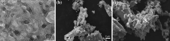
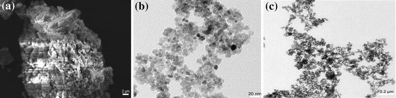
Figure 5 shows the morphologies of FeTiO3, C-TiO2, and CTFTO-10 obtained by SEM and TEM. In the SEM image of the FeTiO3 (Fig.5a), irregular agglomerated particles were observed. Figure 5b shows the TEM image of the C-TiO2, and the particles were spherical in shape, individual as well as a very few number of aggregates with a size of around 10-15 nm, whereas in CTFTO-10 (Fig.5c), few FeTiO3 particles were uniformly distributed on the C-TiO2 surface, which indicates the formation of heterojunction between FeTiO3 and C-TiO2 particles. In addition to this, EDS was used to determine the chemical compositions of the synthesized samples. According to the recorded EDS pattern, FeTiO3 consists of iron, titanium, and oxygen elements only (Fig.6a), and C-TiO2 contains only carbon, titanium, and oxygen elements (Fig.6b), whereas CTFTO-10 contains iron, titanium, oxygen, and carbon elements (Fig.6c), which may confirm the formation of C-TiO2/FeTiO3 heterojunction.
Fig.6 EDS of FeTiO3 a, C-TiO2 b, and CTFTO-10 composite c
3.6 Photocatalytic Performance
Figure 7a shows the photocatalytic degradation of MO over undoped TiO2, C-TiO2, FeTiO3, and C-TiO2/FeTiO3 composites under sunlight irradiation. As shown in Fig.7a, no obvious degradation was observed when FeTiO3 was used as a photocatalyst, which can be ascribed to its rapid recombination rate of photogenerated electron-hole pairs inside the FeTiO3 particles before reaching the surface [27]. However, undoped TiO2 and C-TiO2 show a weak activity (52.7%, 73.3% after 150 min). Compared to pure FeTiO3 and C-TiO2, C-TiO2/FeTiO3 composites were exhibited improved photocatalytic efficiency. The photocatalytic activity decreased gradually with increasing amount of FeTiO3. This may be due to the fact that when the amount of FeTiO3 is higher than 10 wt%, the surface of C-TiO2 is covered by FeTiO3, thus hindering the light absorption ability of C-TiO2 and prevented from forming active heterojunctions [22]. The enhanced photocatalytic activity of C-TiO2/FeTiO3 composites was attributed to the high separation efficiency of photogenerated electron-hole pairs resulted from the formation of the C-TiO2/FeTiO3 heterojunction [22]. As shown in Fig.7a, MO self-photolysis without catalyst under sunlight irradiation was not observed after 150 min, indicating that MO is stable under sunlight irradiation. Figure 7b shows the MO degradation absorption spectra in the presence of CTFTO-10 under sunlight irradiation. The absorption intensity of MO significantly decreases with the increase in irradiation time and nearly disappears after 150 min. The kinetics of photocatalytic degradation of organic pollutants usually follows the Longmuir-Hinshelwood model. If the reactant concentration is low, the fallowing rate equation followed,
,
where C0 and Ct are the concentrations of the MO in solution at time 0 and t, respectively, k is apparent first-order rate constant, and t is the reaction time [27]. The plot of ln (Ct/C0) versus irradiation time (t) is shown in Fig.7c, and the apparent rate constants were 0.0300, 0.0158, 0.0115, 0.0088, 0.0049, and 0.00007 for CTFTO-10, CTFTO-20, CTFTO-40, C-TiO2, and FeTiO3, respectively. This result shows that the introduction of FeTiO3 could efficiently enhance the photocatalytic capability of C-TiO2 under sunlight irradiation.
Fig.7 MO photolysis and photocatalytic degradation over undoped TiO2, FeTiO3, C-TiO2, and C-TiO2/FeTiO3 composites a; UV-Vis absorption spectra for the degradation of MO in the presence of CTFTO-10 composite b and photocatalytic degradation kinetics of undoped TiO2, FeTiO3, C-TiO2, and CTFTO-10 composite for MO degradation under sunlight irradiation c
3.7 Stability and Reusability
In order to evaluate the stability of CTFTO-10 during photocatalytic reaction, cycling experiments were also carried out by repeated decomposition of MO for three times under sunlight irradiation. As shown in Fig.8a, the photocatalytic activity of CTFTO-10 is high even with three cycles with a slight decrease, which could be due to the loss of the sample during the recycling experiments. Figure 8b shows the XRD patterns of the CTFTO-10 composite before and after photocatalytic reaction, and there is no observable structural difference in the samples before and after the reaction, indicating that the phase and structure of CTFTO-10 composite are stable during the photocatalytic reactions. These results indicate that the as-prepared composite catalysts are stable and reusable for photocatalytic reactions.
Fig.8 Reusability study of CTFTO-10 composite for MO degradation under sunlight irradiation a; XRD patterns of the CTFTO-10 composite before and after photocatalytic reactions b
3.8 Role of Reactive Species
Figure 9a shows the photocatalytic degradation results in the presence of different scavengers under sunlight irradiation. The degradation efficiency of MO decreased slightly upon addition of AO compared with the absence of scavenger, which indicated the photogenerated holes are not the main active species for degradation of MO, nor the sources of· OH. When BQ was used as a· O2- scavenger, a dramatic change in the photocatalytic activity was observed compared with the absence of scavenger, confirming that the dissolved oxygen has a clear effect on the photodegradation process under sunlight irradiation. However, a similar change in the photocatalytic activity was observed upon the addition of IPA as a· OH scavenger, which indicates that the· O2- and· OH radicals are the main reactive species in the C-TiO2/FeTiO3 system. Moreover, PL spectra of TA were used to disclose the formation of· OH on the surface of photocatalyst, as shown in Fig.9b. The· OH reacts with TA to form 2-hydroxyterephthalic acid, which emits a characteristic fluorescence signal at 425 nm and gradually increased with the irradiation time [33], which indicates the formation of· OH under sunlight irradiation.
Fig.9 Effect of different scavengers on degradation of MO in the presence of CTFTO-10 composite under sunlight irradiation a; · OH trapping PL spectra of CTFTO-10 composite in TA solution under sunlight irradiation b
3.9 Proposed Mechanism
On the basis of above results, a possible photocatalytic mechanism for the photodegradation of MO over C-TiO2/FeTiO3 photocatalyst under sunlight irradiation is proposed, as shown in Fig.10. The conduction band (CB) and valance band (VB) edge potentials of a semiconductor can be determined by using the following equation
χ -Ee
where χ is the absolute electronegativity of the semiconductor (for TiO2, χ is 5.84 eV) [35], Ee is the energy of free electrons on the hydrogen scale (~4.5 eV), and Eg is the band gap energy of the semiconductor. According to the previous reports, the band gap of FeTiO3 was reported to be in the range of 2.5-2.9 eV, and CB and VB redox potentials are ~0.0 and 2.6 eV, respectively [24, 28]. The calculated CB and VB redox potentials of the undoped TiO2 are -0.245 eV and 2.925 eV. It is well known that nonmetal doping does not change the CB position of TiO2. The VB position of C-TiO2 can be calculated based on the calculated CB position of undoped TiO2 and Eg of C-TiO2 [35, 38], which was found to be 2.579 eV. Under sunlight irradiation, both C-TiO2 and FeTiO3 are excited followed by the formation of electrons and holes in the CB and VB, respectively. Then, the photogenerated electrons can easily migrate from the CB of C-TiO2 to the CB of FeTiO3 because the CB potential of C-TiO2 (-0.245 eV vs. NHE) is more negative than that of FeTiO3 (~0.0 eV vs. NHE) [27]. On the other hand, the VB potential of FeTiO3 (2.6 eV vs. NHE) is more positive than that of C-TiO2 (2.579 eV vs. NHE), so the photogenerated holes in the VB of FeTiO3 can migrate to the VB of C-TiO2. This is due to the synergistic effects at interface of the C-TiO2 and FeTiO3. Similar electron-hole transfer mechanism was reported for C-TiO2/V2O5 composite [17]. This process could effectively improve the separation of photogenerated electron-hole pairs and decrease the possibility of charge recombination further improving the photodegradation efficiency. The electrons in the CB of FeTiO3 reach the surface of photocatalyst to react with adsorbed oxygen to generate various reactive species (· O2- and· OH), while the holes on VB of C-TiO2 react with adsorbed water to produce· OH. These radicals are highly responsible for the degradation of organic pollutants [19, 44].
Fig.10 A schematic mechanism of MO degradation over CTFTO-10 composite under sunlight irradiation
To further increase the photocatalytic activity, a double-heterojunctioned structure of CQD/C-TiO2/FeTiO3 was prepared by loading CQD onto the surface of the CTFTO-10 composite [45]. Figure 11 shows the morphologies of CQD, CTFTO-10, and CQD/CTFTO-10. Figure 11a shows the TEM image of the CQD. The as-prepared CQD was monodispersed with an average size of 10 nm. The SEM image of CTFTO-10 (Fig.11b) remains unchanged even after loading of CQD (CQD/CTFTO-10) (Fig.11c). Figure 12 shows the UV-Vis DRS, XRD, and PL spectra of the CTFTO-10 and CQD/CTFTO-10, respectively. CQD/CTFTO-10 displays strong absorption in the visible region compared with CTFTO-10 (Fig.12a), which implies that the photocatalyst may have higher photocatalytic activity for MO degradation and CQD may be playing an important role in utilizing sunlight [46]. The XRD pattern of CQD/CTFTO-10 shows similar diffraction peaks as CTFTO-10 (Fig.12b). As shown in Fig.12b, no diffraction peaks corresponding to CQD can be found, which is due to the small quantity of CQD in the composite and their poor crystallinity [47]. The PL intensity of CQD/CTFTO-10 was lower than that of CTFTO-10 (Fig.12c), which indicates that after the formation of a double heterojunction, the recombination rate of the photogenerated electron-hole pairs on the photocatalyst surface was suppressed and improved the photocatalytic activity.
Fig.12 Diffuse reflectance UV-Vis spectra a, XRD pattern b, PL spectra c of CTFTO-10 composite and CQD/C-TiO2/FeTiO3 composite
The photocatalytic activity of CQD/CTFTO-10 composite was evaluated for the degradation of MO under sunlight irradiation, which is shown in Fig.13. CQD/CTFTO-10 composite exhibited the highest photocatalytic activity than that of CTFTO-10. MO was almost degraded in 120 min with CQD/CTFTO-10, whereas only 92% MO was degraded for CTFTO-10 within the same time. During the photocatalytic process, CQD can act as both electron acceptors and donors; therefore, the photogenerated electrons in CQD can be easily transferred to the surface of C-TiO2/FeTiO3, and the electrons on C-TiO2/FeTiO3 can also be transferred to CQD [46]. This transference efficiently suppresses the charge recombination and thus results in an enhanced photocatalytic activity. It is consistent with the PL results. Then, the photogenerated electron-hole pairs react with the adsorbed oxygen and water molecules to produce· O2- and· OH radicals, which subsequently cause the degradation of organic pollutants [19, 44].
Fig.13 Photocatalytic degradation of MO over CTFTO-10 composite and CQD/CTFTO-10 composite
4 Conclusions
C-TiO2/FeTiO3 photocatalysts were synthesized with different weight fractions of FeTiO3 for degradation of MO. The XRD results proved that two phases of C-TiO2 and FeTiO3 coexisted in the composites. The absorption edge of the C-TiO2/FeTiO3 composites shifted significantly to longer wavelengths compared to C-TiO2. The PL spectra indicate that the formation of C-TiO2/FeTiO3 composites decreases the recombination of photogenerated electron-hole pairs. All the C-TiO2/FeTiO3 composites showed excellent photocatalytic activities than that of pure samples for the degradation of MO under sunlight irradiation. These results indicate that the formation of heterostructure with intimate contacts between C-TiO2 and FeTiO3 resulted in the easier charge transfer and more efficient separation of electron-hole pairs, which finally improved the photocatalytic activities of the composites. Cyclic experiments indicate the reusability and stability of the CTFTO-10 composite. The study on the photocatalytic mechanism of the CTFTO-10 composite implies that· O2- and· OH radicals should be the main active species involved in the MO degradation process. Based on the results obtained in this study, a possible photocatalytic mechanism of CTFTO-10 composite under sunlight irradiation was proposed. In order to enhance the photocatalytic efficiency, a double-heterojunctioned CQD/CTFTO-10 composite was prepared, and its mechanism was also discussed.
Acknowledgments
One of the authors (D. Ramakrishna, SRF) gratefully acknowledges the University Grants Commission (UGC), New Delhi, India, for financial support with Ref. No.: 17-06/2012(i)EU-V. The authors wish to thank Centre for Nanotechnology, University of Hyderabad, for their TEM facility.
The authors have declared that no competing interests exist.
Z. B. Wu, F. Dong, Y. Liu, H. Q. Wang, Catal. Commun. 11, 82(2009)[Cite with in:4]
[18]
Q. Li, Y. W. Li, P. Wu, R. Xie, J. K. Shang, Adv. Mater. 20, 3717(2008)[Cite with in:1]
[19]
T. Jayaraman, S. A. Raja, A. Priya, M. Jagannathan, M. Ashokkumar, New J. Chem. 39, 1367(2015)[Cite with in:3]
[20]
Z. Zhang, W. Z. Wang, L. Wang, S. Sun, Appl. Mater. Interfaces4, 593 (2012)[Cite with in:1]
[21]
H. J. Liu, Y. L. Wang, G. G. Liu, Y. Ren, N. Zhang, G. Wang, T. Li, Acta Metall. Sin. (Engl. Lett. ) 27, 149(2014)[Cite with in:1]
[22]
M. E. Zarazúa-Morín, L. M. Torres-Martínez, E. Moctezuma, I. Juárez-Ramírez, B. B. Zermeño, Synthesis, characterization, catalytic activity of FeTiO3/TiO2 for photodegradation of organic pollutants with visible light. Res. Chem. Intermed. (2015). doi: DOI:10.1007/s11164-015-2071-9[Cite with in:4]
[23]
J. J. Ru, Y. Hua, C. Xu, J. Li, Y. Li, D. Wang, K. Gong, R. Wang, Z. Zhou, Ceram. Int. 40, 6799(2014)[Cite with in:1]
[24]
Y. J. Kim, B. Gao, S. Y. Han, M. H. Jung, A. K. Chakraborty, T. Ko, C. Lee, W. I. Lee, J. Phys. Chem. C113, 19179 (2009)[Cite with in:3]
[25]
F. Liu, H. He, C. B. Zhang, Novel iron titanate catalyst for the selective catalytic reduction of NO with NH3 in the medium temperature range. Chem. Commun. (2008). doi: DOI:10.1039/B800143J[Cite with in:1]
[26]
Y. H. Chen, J. Non Cryst. Solids357, 136 (2011)[Cite with in:1]
[27]
S. Sivakumar, A. Selvaraj, A. K. Ramasamy, V. Balasubramanian, Water Air Soil Pollut. 224, 1529(2013)[Cite with in:6]
[28]
B. Gao, Y. J. Kim, A. K. Chakraborty, W. I. Lee, Appl. Catal. B Environ. 83, 202(2008)[Cite with in:3]
[29]
Q. D. Truong, J. Y. Liu, C. C. Chung, Y. C. Ling, Catal. Commun. 19, 85(2012)[Cite with in:1]
[30]
D. K. Devi, S. V. Pratap, R. Haritha, K. S. Sivudu, P. Radhika, B. Sreedhar, J. Appl. Polym. Sci. 121, 1765(2011)[Cite with in:1]
[31]
H. Li, R. Liu, Y. Liu, H. Huang, H. Yu, H. Ming, S. Lian, S. T. Lee, Z. Kang, J. Mater. Chem. 22, 17470(2012)[Cite with in:1]
[32]
S. Palla, G. Ravi, R. Velchuri, N. K. Veldurthi, J. R. Reddy, V. Muga, J. Sol-Gel. Sci. Technol. 75, 224(2015)[Cite with in:1]
[33]
B. Cheng, Y. Le, J. Yu, J. Hazard. Mater. 177, 971(2010)[Cite with in:2]
X. C. Sun, C. Bruckner, M. P. Nieh, Y. Lei, J. Mater. Chem. A2, 14613 (2014)[Cite with in:1]
[37]
F. Dong, H. Q. Wang, Z. B. Wu, J. Phys. Chem. C113, 16717 (2009)[Cite with in:4]
[38]
Y. Huang, W. Ho, S. C. Lee, L. Zhang, G. Li, J. C. Yu, Langmuir24, 3510 (2008)[Cite with in:2]
[39]
C. Chen, Q. W. Liu, S. Gao, K. Li, H. Xu, Z. Z. Lou, B. B. Huang, Y. Dai, RSC Adv. 4, 12098(2014)[Cite with in:1]
[40]
X. Tang, K. A. Hu, J. Mater. Sci. 41, 8025(2006)[Cite with in:1]
[41]
A. B. Gambhire, M. K. Land e, S. B. Rathod, B. R. Arbad, K. N. Vidhate, R. S. Gholap, K. R. Patil, Synthesis and characterization of FeTiO3 ceramics. Arab. J. Chem. (2011). doi: DOI:10.1016/j.arabjc.2011.05.012[Cite with in:1]
[42]
T. Wang, G. Yang, J. Liu, B. Yang, S. Ding, Z. Yan, T. Xiao, Appl. Surf. Sci. 311, 314(2014)[Cite with in:1]
[43]
M. A. Subhan, M. R. Awal, T. Ahmed, M. Younus, Acta Metall. Sin. (Engl. Lett. ) 27, 223(2014)[Cite with in:1]
[44]
S. Palla, R. Guje, G. Ravi, R. Velchuri, M. Vithal, Acta Metall. Sin. (Engl. Lett. ) 28, 216(2015)[Cite with in:2]
[45]
S. Bera, S. B. Rawal, H. J. Kim, W. I. Lee, Appl. Mater. Interfaces6, 9654 (2014)[Cite with in:1]
[46]
H. C. Zhang, H. Huang, H. Ming, H. Li, L. Zhang, Y. Liu, Z. H. Kang, J. Mater. Chem. 22, 10501(2012)[Cite with in:2]
[47]
Y. Q. Zhang, D. K. Ma, Y. G. Zhang, W. Chen, S. M. Huang, Nano Energy2, 545 (2013)[Cite with in:1]
1
2010
0.0
0.0
W. Kangwansupamonkon, W. Jitbunpot, S. Kiatkamjornwong, Polym. Degrad. Stab. 95, 1894(2010)
... A substantial amount of dyestuff is lost due to inefficiency of dying during the dyeing process, which poses a major problem to the environment [1, 2] ...
... A substantial amount of dyestuff is lost due to inefficiency of dying during the dyeing process, which poses a major problem to the environment [1, 2] ...
1
2014
0.0
0.0
... 2 eV for anatase phase), which largely limits its application range [3] ...
... Sunlight is the most abundantly available, renewable, and clean source of energy, which is composed of ~46% of visible radiation and ~5% of UV radiation [4] ...
1
2012
0.0
0.0
B. Qi, Y. Yu, X. Q. He, L. Z. Wu, X. F. Duan, J. F. Zhi, Mater. Chem. Phys. 135, 549(2012)
... To efficiently use solar energy, many modification methods have been studied to extend the spectral response of TiO2 to the visible region, such as metal doping [5, 6], nonmetal doping [7, 8], semiconductor coupling [9, 10], and surface dye sensitization [11, 12] ...
... To efficiently use solar energy, many modification methods have been studied to extend the spectral response of TiO2 to the visible region, such as metal doping [5, 6], nonmetal doping [7, 8], semiconductor coupling [9, 10], and surface dye sensitization [11, 12] ...
1
2013
0.0
0.0
... To efficiently use solar energy, many modification methods have been studied to extend the spectral response of TiO2 to the visible region, such as metal doping [5, 6], nonmetal doping [7, 8], semiconductor coupling [9, 10], and surface dye sensitization [11, 12] ...
... To efficiently use solar energy, many modification methods have been studied to extend the spectral response of TiO2 to the visible region, such as metal doping [5, 6], nonmetal doping [7, 8], semiconductor coupling [9, 10], and surface dye sensitization [11, 12] ...
1
2007
0.0
0.0
... To efficiently use solar energy, many modification methods have been studied to extend the spectral response of TiO2 to the visible region, such as metal doping [5, 6], nonmetal doping [7, 8], semiconductor coupling [9, 10], and surface dye sensitization [11, 12] ...
1
2013
0.0
0.0
... To efficiently use solar energy, many modification methods have been studied to extend the spectral response of TiO2 to the visible region, such as metal doping [5, 6], nonmetal doping [7, 8], semiconductor coupling [9, 10], and surface dye sensitization [11, 12] ...
Department of Chemical and Biochemical Engineering, University of Western Ontario , London, ON N6A 5B9,Canada *E-mail: aray@eng.uwo.ca . Fax: +1 519 661 3498 .
Phenol degradation with TiO 2 photocatalyst under UV light is known to be an effective method. Under solar radiation, however, this approach does not receive adequate photons for catalyst activation, as the solar spectrum comprises mostly visible light (46%). In this study, we applied the dye-sensitization technique to prepare visible-light-active catalyst and used it under visible solar light generated from a solar simulator with a UV cutoff filter (λ > 420 nm) for phenol degradation. Eosin Y dye was used as a sensitizer for the TiO 2 catalyst with a very low level of platinum as a cocatalyst. Triethanolamine was used as a sacrificial electron donor. Parametric studies were performed for the catalyst loading, initial triethnolamine concentration, initial phenol concentration, platinum content on TiO 2 , solution pH, and visible light intensity. About 93% degradation of 40 ppm phenol solution was achieved within 90 min using Eosin Y–TiO 2 /Pt photocatalyst under optimum conditions (pH 7.0, catalyst loading of 0.8 g/L, triethnolamine concentration of 0.2 M, 0.5% Pt loading on TiO 2 , visible solar light intensity of 100 mW/cm 2 ). The kinetic rate constant and adsorption equilibrium constant were determined, and a Langmuir–Hinshelwood-type equation was proposed to describe phenol degradation on TiO 2 at different visible light intensities. The model equation was found to predict the experimental results quite well.
... To efficiently use solar energy, many modification methods have been studied to extend the spectral response of TiO2 to the visible region, such as metal doping [5, 6], nonmetal doping [7, 8], semiconductor coupling [9, 10], and surface dye sensitization [11, 12] ...
1
2013
0.0
0.0
... To efficiently use solar energy, many modification methods have been studied to extend the spectral response of TiO2 to the visible region, such as metal doping [5, 6], nonmetal doping [7, 8], semiconductor coupling [9, 10], and surface dye sensitization [11, 12] ...
1
2011
0.0
0.0
... Nonmetal doping, such as carbon [13] or nitrogen [14], has displayed promising results in shifting the light absorption of TiO2 into visible region ...
1
2012
0.0
0.0
D. Nassoko, Y. F. Li, H. Wang, J. L. Li, Y. Z. Li, Y. Yu, J. Alloys Compd. 540, 228(2012)
... Nonmetal doping, such as carbon [13] or nitrogen [14], has displayed promising results in shifting the light absorption of TiO2 into visible region ...
... As far as visible light photocatalytic activity is concerned, C-doped TiO2 was found to be more active than N-doped TiO2 [15,16,17] ...
... However, after carbon doping, the PL intensity was decreased, indicating that the carbon doping can effectively inhibit the recombination of photogenerated electron-hole pairs in C-TiO2 [16] ...
4
2009
0.0
0.0
Z. B. Wu, F. Dong, Y. Liu, H. Q. Wang, Catal. Commun. 11, 82(2009)
... As far as visible light photocatalytic activity is concerned, C-doped TiO2 was found to be more active than N-doped TiO2 [15,16,17] ...
... From the viewpoint of practical application, higher photocatalytic reaction efficiency is required since the photocatalytic efficiency of nonmetal-doped TiO2 under visible light is still low [17, 18] ...
... Similar results were also observed in previous report [17] ...
... Similar electron-hole transfer mechanism was reported for C-TiO2/V2O5 composite [17] ...
1
2008
0.0
0.0
Q. Li, Y. W. Li, P. Wu, R. Xie, J. K. Shang, Adv. Mater. 20, 3717(2008)
... From the viewpoint of practical application, higher photocatalytic reaction efficiency is required since the photocatalytic efficiency of nonmetal-doped TiO2 under visible light is still low [17, 18] ...
3
2015
0.0
0.0
... Recently, coupling of semiconductor with other semiconductor to form a heterojunction structure has been widely used to enhance the photocatalytic performance of photocatalysts [19,20,21] ...
... These radicals are highly responsible for the degradation of organic pollutants [19, 44] ...
... OH radicals, which subsequently cause the degradation of organic pollutants [19, 44] ...
1
2012
0.0
0.0
... Recently, coupling of semiconductor with other semiconductor to form a heterojunction structure has been widely used to enhance the photocatalytic performance of photocatalysts [19,20,21] ...
1
2014
0.0
0.0
... Recently, coupling of semiconductor with other semiconductor to form a heterojunction structure has been widely used to enhance the photocatalytic performance of photocatalysts [19,20,21] ...
4
2015
0.0
0.0
... 9 having potential applications in electronic circuits, solar cells, gas sensors, and photocatalysis [22] ...
... Up to now, a few FeTiO3/TiO2 photocatalysts have been prepared for photocatalytic performance under UV and visible light [22, 24, 27,28,29] ...
... This may be due to the fact that when the amount of FeTiO3 is higher than 10 wt%, the surface of C-TiO2 is covered by FeTiO3, thus hindering the light absorption ability of C-TiO2 and prevented from forming active heterojunctions [22] ...
... The enhanced photocatalytic activity of C-TiO2/FeTiO3 composites was attributed to the high separation efficiency of photogenerated electron-hole pairs resulted from the formation of the C-TiO2/FeTiO3 heterojunction [22] ...
1
2014
0.0
0.0
J. J. Ru, Y. Hua, C. Xu, J. Li, Y. Li, D. Wang, K. Gong, R. Wang, Z. Zhou, Ceram. Int. 40, 6799(2014)
... In the earlier studies, FeTiO3 was prepared by microwave [23], hydrothermal [24], co-precipitation [25], and sol-gel [26] methods, etc ...
3
2009
0.0
0.0
... In the earlier studies, FeTiO3 was prepared by microwave [23], hydrothermal [24], co-precipitation [25], and sol-gel [26] methods, etc ...
... Up to now, a few FeTiO3/TiO2 photocatalysts have been prepared for photocatalytic performance under UV and visible light [22, 24, 27,28,29] ...
... 6 eV, respectively [24, 28] ...
1
2008
0.0
0.0
... In the earlier studies, FeTiO3 was prepared by microwave [23], hydrothermal [24], co-precipitation [25], and sol-gel [26] methods, etc ...
1
2011
0.0
0.0
... In the earlier studies, FeTiO3 was prepared by microwave [23], hydrothermal [24], co-precipitation [25], and sol-gel [26] methods, etc ...
6
2013
0.0
0.0
S. Sivakumar, A. Selvaraj, A. K. Ramasamy, V. Balasubramanian, Water Air Soil Pollut. 224, 1529(2013)
1. Department of Chemistry, Periyar University, Salem, 636 011, India 2. Department of Chemistry and Environmental Sciences, AMET University, Kanathur, Chennai, 603 112, India
... Up to now, a few FeTiO3/TiO2 photocatalysts have been prepared for photocatalytic performance under UV and visible light [22, 24, 27,28,29] ...
... 61 corresponding the lattice planes (012), (104), (110), and (024), respectively [27] ...
... 1c), which may be because of low amount of FeTiO3 and uniform dispersion on the surface of C-TiO2 [27] ...
... 7a, no obvious degradation was observed when FeTiO3 was used as a photocatalyst, which can be ascribed to its rapid recombination rate of photogenerated electron-hole pairs inside the FeTiO3 particles before reaching the surface [27] ...
... where C0 and Ct are the concentrations of the MO in solution at time 0 and t, respectively, k is apparent first-order rate constant, and t is the reaction time [27] ...
... Up to now, a few FeTiO3/TiO2 photocatalysts have been prepared for photocatalytic performance under UV and visible light [22, 24, 27,28,29] ...
... 2a), which subsequently results in the efficient utilization of visible light for the photocatalytic reaction [28] ...
... 6 eV, respectively [24, 28] ...
1
2012
0.0
0.0
Q. D. Truong, J. Y. Liu, C. C. Chung, Y. C. Ling, Catal. Commun. 19, 85(2012)
... Up to now, a few FeTiO3/TiO2 photocatalysts have been prepared for photocatalytic performance under UV and visible light [22, 24, 27,28,29] ...
1
2011
0.0
0.0
D. K. Devi, S. V. Pratap, R. Haritha, K. S. Sivudu, P. Radhika, B. Sreedhar, J. Appl. Polym. Sci. 121, 1765(2011)
... GA is a highly branched, neutral or slightly acidic arabinogalactan polysaccharide obtained naturally from the stems and branches of the Acacia Senegal tree [30] ...
1
2012
0.0
0.0
... 5 Synthesis of Carbon Quantum Dots (CQD)CQD were synthesized according to the literature [31], followed by freeze drying to get powder ...
1
2015
0.0
0.0
S. Palla, G. Ravi, R. Velchuri, N. K. Veldurthi, J. R. Reddy, V. Muga, J. Sol-Gel. Sci. Technol. 75, 224(2015)
1. Department of Chemistry, Osmania University, Hyderabad, 500 007, India
... 2 g, hole (h+) scavenger] were added to the MO solution [32] ...
... Then, the suspension was subjected to sunlight irradiation, and the PL intensity was measured using a spectrofluorophotometer at an excitation wavelength of 315 nm [33] ...
... OH reacts with TA to form 2-hydroxyterephthalic acid, which emits a characteristic fluorescence signal at 425 nm and gradually increased with the irradiation time [33], which indicates the formation of#cod#x000b7 ...
... The diffraction peaks of C-TiO2 were broader with low intensity compared to undoped TiO2, indicating the decrease in crystallite size due to the incorporation of carbon atoms into the TiO2 lattice [35] ...
... 84 eV) [35], Ee is the energy of free electrons on the hydrogen scale (~4 ...
... The VB position of C-TiO2 can be calculated based on the calculated CB position of undoped TiO2 and Eg of C-TiO2 [35, 38], which was found to be 2 ...
1
2014
0.0
0.0
... is photon energy, and Eg is band gap [36] ...
4
2009
0.0
0.0
... 17 eV for undoped TiO2) by modifying the valance band [37, 38] ...
... The broad peaks around 3400-3200 cm-1 and sharp peaks at 1630 cm-1 are associated with the stretching and bending vibration of surface-adsorbed water and hydroxyl groups of all the samples [37] ...
... The surface hydroxyl groups play an important role in the photocatalytic process, as these groups can be trapped by the holes generated under sunlight irradiation to form hydroxyl radicals which can suppress electron-hole recombination, hence increase the photocatalytic efficiency [37] ...
... The PL emission is obtained as a result of recombination of excited electron-hole pair, and hence, lower PL intensity indicates efficient charge carrier separation [37, 43] ...
2
2008
0.0
0.0
... 17 eV for undoped TiO2) by modifying the valance band [37, 38] ...
... The VB position of C-TiO2 can be calculated based on the calculated CB position of undoped TiO2 and Eg of C-TiO2 [35, 38], which was found to be 2 ...
1
2014
0.0
0.0
... The peaks in the region from 400 to 800 cm-1 of C-TiO2 are corresponding the asymmetric, symmetric stretching, and the bending mode of Ti-O-Ti bond [39] ...
1. School of Material Science and Engineering, Shanghai Jiao Tong University, 1954, Huashan Road, Shanghai, 200030, P.R. China
... In the FTIR spectrum of FeTiO3, a wide band from 400 to 650 cm-1 was observed that corresponds to the metal-oxygen bond [40, 41] ...
1
2011
0.0
0.0
... In the FTIR spectrum of FeTiO3, a wide band from 400 to 650 cm-1 was observed that corresponds to the metal-oxygen bond [40, 41] ...
1
2014
0.0
0.0
T. Wang, G. Yang, J. Liu, B. Yang, S. Ding, Z. Yan, T. Xiao, Appl. Surf. Sci. 311, 314(2014)
... In addition, a wide band ranging from 400 to 800 cm-1 was also observed in the FTIR spectra of all the C-TiO2/FeTiO3 composites, which can be assigned to the overlapping peak between the Ti-O-Ti bond and Fe-O bonds, indicating the coexistence of FeTiO3 and C-TiO2 [42] ...
1
2014
0.0
0.0
... The PL emission is obtained as a result of recombination of excited electron-hole pair, and hence, lower PL intensity indicates efficient charge carrier separation [37, 43] ...
2
2015
0.0
0.0
... These radicals are highly responsible for the degradation of organic pollutants [19, 44] ...
... OH radicals, which subsequently cause the degradation of organic pollutants [19, 44] ...
1
2014
0.0
0.0
... To further increase the photocatalytic activity, a double-heterojunctioned structure of CQD/C-TiO2/FeTiO3 was prepared by loading CQD onto the surface of the CTFTO-10 composite [45] ...
2
2012
0.0
0.0
... 12a), which implies that the photocatalyst may have higher photocatalytic activity for MO degradation and CQD may be playing an important role in utilizing sunlight [46] ...
... therefore, the photogenerated electrons in CQD can be easily transferred to the surface of C-TiO2/FeTiO3, and the electrons on C-TiO2/FeTiO3 can also be transferred to CQD [46] ...
1
2013
0.0
0.0
... 12b, no diffraction peaks corresponding to CQD can be found, which is due to the small quantity of CQD in the composite and their poor crystallinity [47] ...
Synthesis and Characterization of C-TiO2/FeTiO3 and CQD/C-TiO2/FeTiO3 Photocatalysts with Enhanced Photocatalytic Activities Under Sunlight Irradiation


 ]
]