Three high-nitrogen stainless steels with different N contents were successfully processed by equal-channel angular pressing for one pass, and their microstructures and mechanical properties were investigated. It was found that the microstructure of the billet was heterogeneous across the billet thickness, resulting in the difference in the mechanical properties due to the different deformation conditions. A relatively low strength, high uniform elongation, and high work-hardening rate for the samples at the bottom of the billet was achieved in comparison with those processed at the top. Meanwhile, it was observed that the density of deformation twins increased with the content of N; accordingly, the strength and elongation of the alloys increase with the content of N, resulting in a good strength-ductility combination.
High-nitrogen austenitic stainless (HNS) steel has emerged as a promising group of structural materials that possess a favorable combination of mechanical properties and corrosion resistance [1]. Nitrogen has strong influence on solid solution hardening, which may be attributed to the atomic size misfit of the N atoms with the austenite crystal lattice. It has the greatest effect on yield strength among the alloying elements [2]. On the other hand, N is a strong austenite stabilizer and retards the onset of TRIP (transformation-induced plasticity). Therefore, appropriate addition of N is critical to achieve the best comprehensive mechanical properties. The addition of interstitial N has been reported to increase significantly the flow stress of polycrystalline austenitic stainless steels [3, 4, 5]. Similar results have also been reported in the studies conducted on Hadfield steel single crystals [6] and austenitic stainless steel single crystals [7, 8, 9].
However, their low yield strength is still a major drawback. To further strengthen the stainless steel, microstructure grain refinement is an effective approach [10, 11]. It is now well established that processing through the application of severe plastic deformation (SPD), typically, equal-channel angular pressing (ECAP), is especially effective in grain refinement for those bulk polycrystalline metals [11]. Up to date, this method has been successfully used to produce several ultrafine-grained (UFG) steels [12, 13]. As a result, the UFG steels exhibited superior mechanical properties, such as high strength and sometimes good ductility, compared with their coarse-grained (CG) counterparts.
In order to produce UFG and nanocrystalline (NC) materials with desirable microstructures and mechanical properties, it is crucial to understand the microstructure evolution processes induced by SPD. Up to now, there is lack of report about the microstructural evolution and mechanical properties of HNS steels during ECAP. Accordingly, the present investigation was motivated by two considerations. First, a study on the heterogeneity of mechanical properties, paired with microstructure investigations in low-SFE (stacking fault energy) materials after ECAP, is important for a better understanding on their fundamental physical properties, the trends, and limits of their prospective engineering applications. Second, a systematic investigation of the evolution of the microstructures in the HNS steels during ECAP processing contributes to an extension of our current knowledge of structure control during materials processing.
2 Experimental
The materials studied in the present work, named as HNSS-65, HNSS-83, and HNSS-99, were produced by vacuum induction melting and followed by electro-slag remelting in nitrogen atmosphere with compositions as listed in Table 1. Then, the HNS steel ingots were hot-forged and hot-rolled into sheets with thickness of 12 mm. Before ECAP procedure, round cylindrical billets (8 mm in diameter and 45 mm in length) cut from those sheets by means of electrical discharge machining (EDM) were sealed in a quartz tube under vacuum and solution-treated at 1100 ° C for 4 h in the austenite single-phase region, followed by water quenching.
Table 1
Table 1
Table 1 Chemical compositions of austenitic stainless steels (wt%)
C
Mn
Si
Cr
N
Mo
P
S
HNSS-65
0.017
15.7
0.28
18.24
0.83
2.26
0.005
0.003
HNSS-83
0.044
15.8
0.18
18.62
0.65
2.78
0.013
0.004
HNSS-99
0.020
16.1
0.31
17.98
0.99
2.27
0.005
0.003
Table 1 Chemical compositions of austenitic stainless steels (wt%)
The ECAP procedure was performed using a die fabricated from tool steel with two channels intersecting at an inner angle of 120° and an outer angle of 30° , as illustrated in Fig. 1a, accordingly yielding an effective strain of ~0.628 for each pass. All the rods coated with a MoS2 lubricant were processed at room temperature (RT) with a pressing speed of 9 mm min-1.
Fig. 1 a Schematic illustration of a billet before and after ECAP for a single pressing through the die; b illustration of billet for ECAP and the coordinate systems; c illustration of tensile specimen; d selected positions for tensile specimens on the transverse section of the ECAP billet
Microstructures of the annealed and ECAP-processed samples were characterized by using electron backscattered diffraction (EBSD, the step size is 1 μ m) with scanning electron microscopy (SEM, LEO SUPRA 35) operated at 20 kV, and transmission electron microscopy (TEM, FEI Tecnai F20) operated at 200 kV, respectively. For microscopic observations, the samples were mechanically polished using diamond paste and then electro-etched at RT in a solution of 10 g oxalic acid and 90 ml refined water (10 wt% oxalic acid solutions). The electro-etched current density is 0.6-1 A cm-2 with a holding time of 60-90 s. Thin foils for TEM observations, cut from the Z-plane in the centers of the pressed rods using spark cutting, were mechanically ground to about 50 mm thick and then thinned by a twin-jet polishing method in an electrolyte consisting of 8% perchloric acid and 92% alcohol at -15 ° C.
The Vickers microhardness was measured on the polished cross-sectional planes of as-pressed billet on a LM247AT microhardness tester with a load of 100 g for a loading time of 15 s. The hardness values obtained were averaged from at least 10 indents for each sample. Tensile specimens with a dog-bone shape were cut into a gauge length of 8 mm, with a width of 2 mm and a thickness of 1 mm from the processed billets along the extrusion direction of ECAP, as shown in Fig. 1c, d. Tensile tests were carried out at RT using an Instron 5982 testing machine operating at a strain rate of 10-3 s-1 for the ECAP-processed specimens.
3 Results and Discussion
3.1 Microstructure Characterization
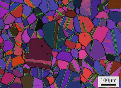
Figure 2 shows the microstructures of the HNSS-83 steels after hot-rolling and annealing at 1100 ° C for 4 h. It reveals fully austenite phase with the average grain size of 50-100 μ m as well as some annealing twins.
Fig. 2 Microstructure of the as-received HNS steel was characterized by EBSD
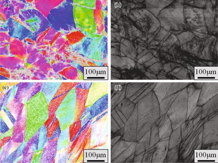
Figure 3 presents the typical microstructures of the samples HNSS-83 after ECAP at top and bottom positions of the billet. The microstructure after one-pass ECAP is inhomogeneous, as is commonly observed in fcc metals at this strain. The deformation microstructures mainly consist of slightly elongated grains, as well as very high density of parallel strips in the interior of some grains, which were identified as deformation twins in the form of bundles from TEM observations [14, 15]. Besides the deformation twins, some shear bands with different width can also be observed occasionally as shown in Fig. 3b. They were often observed in the twinned grains when homogeneous plastic deformation could not sustain work-hardening with increasing strain. The localized deformation mode initially appears within narrow bands. Some of the bubble twins are bending in shape due to the cutting of the shear banding. With increasing shear strain, the shear bands are broaden to several micrometers thick. The microstructure is characterized mainly by two deformation modes: mechanical twinning and submicron-scaled shear banding [16, 17]. The former leads to profuse mechanical twins with some tens of nanometers in thickness. Almost every grain has been transformed into a twin-matrix lamellar structure. The latter divides the material into a debris-like structure leading to micron-sized blocks of twin-matrix lamellae.
Fig. 3 Microstructure of the HNSS-83 steel characterized by EBSD: a, b at the top of the billet after ECAP; c, d at the bottom of the billet after ECAP
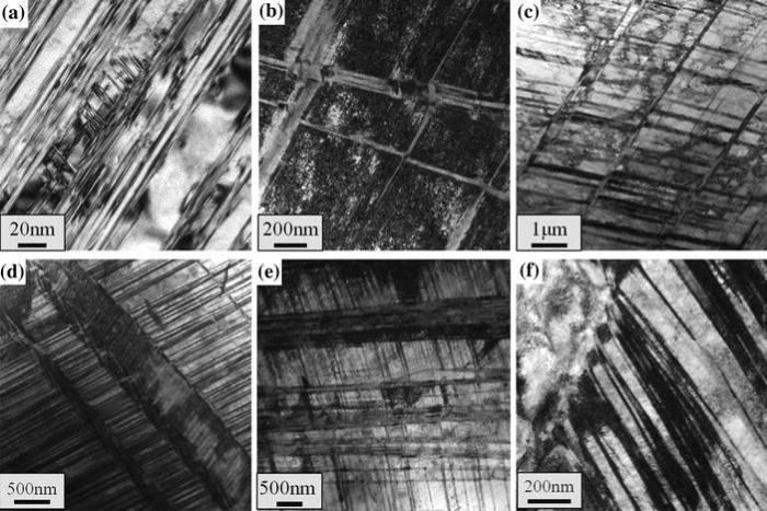
To study the deformation mechanisms and the evolving microstructures during ECAP on a smaller scale, TEM observations were carried out to characterize the deformation microstructures in detail. The dislocation configurations of the sample after ECAP are shown in Fig. 4. At low strain level, substructure developments are manifested by piling-up of dislocations on a single slip plane and slip along the principal crystallographic directions, which are the typical planar glide configurations [18]. Figure 4a, b reveals that the grains without mechanical twins contain a high density of planar dislocation structures. No distinct cell formation was observed, but a Taylor lattice-like structure, a kind of low-energy dislocation structure [19, 20], was formed. Dissociated partial dislocations with the wide stacking fault (SF) are randomly distributed in Fig. 4c. Another TEM micrograph (Fig. 4d) contains the microstructure of wide SF. The dislocation structure at further deformation stage is characterized by planar dislocation arrays formed by high-density dislocation walls (HDDWs) and well-developed microband, exhibiting a very high dislocation density between the ill-defined boundaries (Fig. 4e, f). The formation of HDDWs should result from coplanar slip and orient in the crystallographic < 1 1 1> directions. The number of HDDWs depends on the crystal orientation and the applied stress state. The microbands developed in no cell-forming fcc alloys are formed as a result of intense plastic localization on single or coplanar slip.
Fig. 4 a, b Activation of the limited slip systems with the planar gliding of dislocations and the Taylor lattice formation; c, d dissociated partial dislocations with the wide stacking fault; e, f formation of the HDDWs and microbands
Figure 5 presents typical bright-field TEM micrographs of the twin microstructures for the HNSS-83 billets subjected to ECAP for one pass. Figure 5a shows a magnified TEM image of nanotwin bundles. Deformation twins with very thin thickness of 10-50 nm are widely observed, and most of them appear in the form of bundles. Moreover, twin intersections were also detected in some grains (Fig. 5b). The prevalence of twin in these samples implies that twinning is a dominant deformation mode at such severe processing condition, which is consistent with the observations as shown in Fig. 3. Figure 5c-e reveals the microscale shear band as thin (~ 100 nm) lath-like regions of concentrated plastic deformation [21]. It is interesting to note in Fig. 5f that twin-matrix lamellae are completely vanished within the shear band. This can be attributed to the de-twinning process induced by twin-slip interactions [22]. The presence of above shear band indicates the inhomogeneous deformation behavior of the present steels.
Fig. 5 TEM micrographs of the deformation microstructure of HNS-83 steels after one ECAP pass: a a higher magnification observation of a nanotwin bundle; b twin intersections; c-e the nanotwined regions with shear bands; f twin-matrix lamellae are vanished within the shear band
3.2 Mechanical Property
Typical tensile engineering stress-strain curves of the three HNS steels subjected to ECAP for one pass at different locations of the billets are presented in Fig. 6a-c. The mechanical properties including yield strength (YS), ultimate tensile strength (UTS), and uniform elongation (UE), as a function of the content of N, are summarized in Fig. 6d-f and Table 2. It can be seen that YS, UTS, and UE increase with the N content. Besides, the elongation to failure is low and nearly remains constant from 15% to 30% over all positions in the three samples.
Fig. 6 a-c Typical tensile engineering stress-strain curves of the samples at different locations of the billets; d-emechanical properties, including YS, UTS, and UE, as a function of the N content
Table 2
Table 2
Table 2 Tensile properties of three HNS samples at different locations of the ECAP billets
Distance from center (mm)
-2.25
-0.75
0.75
2.25
HNSS-65
YS (0.2%) (MPa)
950
1030
1132
1201
UTS (MPa)
1151
1121
1214
1303
UE (%)
13.7
7.87
1.91
1.59
HNSS-83
YS (0.2%) (MPa)
1005
1087
1211
1264
UTS (MPa)
1233
1207
1302
1385
UE (%)
15.6
8.91
3.08
1.76
HNSS-99
YS (0.2%) (MPa)
1046
1105
1277
1345
UTS (MPa)
1281
1257
1343
1412
UE (%)
17.6
13.4
3.78
1.83
Table 2 Tensile properties of three HNS samples at different locations of the ECAP billets
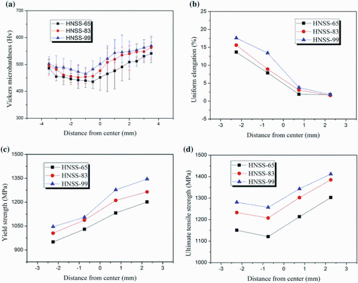
To reveal the variation in mechanical properties due to the inhomogeneous microstructure of the HNS steels after ECAP, the hardnesses were measured at different positions along vertical traverses in the centers of the cross-sectional planes (Fig. 7a). With the same visible trend, the average hardness first decreases slightly and then increases with increasing distance from the center along the Z-direction. However, it is interesting to note that, at the same position of the billet, the HNS steel with higher N content always displays relatively higher hardness than that with lower N. The mechanical properties including YS, UTS, and UE, as a function of the distance from center, are also summarized in Fig. 7b-d. The mechanical properties of the three HNS steels exhibit a similar trend, which is consistent with the evolution of hardness. It is seen that YS and UTS almost increase with increasing distance from center, as well as an obvious drop in UE. Taking HNSS-99 as an example, its YS increases substantially, from 1046 MPa (at the bottom) to 1345 MPa (at the top), while its UTS reaches 1412 MPa at the top. Meanwhile, the UE drops from 17.6% to 1.83%.
Fig. 7 a Values of the Vickers microhardness for HNS steels recorded along the Z-direction on the cross-sectional plane after ECAP; b, c mechanical properties including YS, UTS, and UE, as a function of the distance from center of the billets
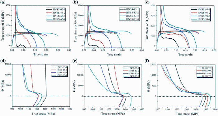
Tensile true stress-true strain curves and work-hardening rates (Θ Θ ) versus true stress curves of the ECAP-processed samples are plotted in Fig. 8. It can be seen that all samples exhibit steep decrease in work-hardening rate when the strain is below 3%, corresponding to the elastic-plastic transition. For the ECAP-processed sample at the bottom, it then decreases with further increasing strain. The decreasing rate of Θ Θ with strain is higher as the distance from center increases. For the ECAP-processed sample at the top, the work-hardening rate drops to zero immediately after the elastic-plastic transition, implying that the microstructure has no any work-hardening capability during plastic deformation.
Fig. 8 Work-hardening rate Θ versus true strain a-c and versus true stress d-f for the HNSS steel samples at different positions of the ECAP billets
It has been widely acknowledged that the ductility of metallic materials is controlled by strain-hardening. In macroscale, the Consideré criterion governs the onset of localized deformation in tension
(1)
where σ is true stress, ε is true strain, and ε ˙ ε ˙ is strain rate of tensile test. According to the Consideré criterion, in principle, plastic instability starts to happen at the UTS, which can determine the UE during tensile plastic deformation, when the increment in strength of the materials is less than the decrease in the load-bearing ability [23]. Therefore, necking cannot occur as long as the Θ Θ value keeps positive with increasing plastic strain, as shown in Fig. 8. As mentioned above, the improvement of ductility can be attributed to the increase in Θ Θ , which is controlled by two components: a dislocation storage (hardening) component and a dynamic recovery (softening) component, related to dislocation annihilation processes [24]. Enhancing Θ Θ , which can be achieved by increasing the hardening component and restricting the softening components, will help delay the localized deformation and is crucial for ameliorating uniform elongation.
The differences in strength variation and strain-hardening behavior can be explained by examining the microstructures of the samples processed at different conditions. As shown in Fig. 3b, the microstructures in the samples at the top of the billet are mainly characterized by lamellar twins and some microscale shear bands. As already noted, the more the twin boundaries are, the higher the strength is [25]. Moreover, the more severe processing conditions will help accumulate higher density dislocations, thereby can provide further strength [26]. Deformation twins arrangement in bundles containing a high dislocation density as well restricts the storing of crystalline defects during the subsequent tensile testing so that the extent of uniform deformation is decreased. Strain localization will then occur more readily, leading to catastrophic failure [27]. Moreover, in contrast to their role in strengthening materials, microscale shear bands provide few contributions for ameliorating the ductility, because the formation of these shear bands has no significant effect on the strain-hardening rate. Therefore, a high strength but low ductility is expected. In contrast, at the bottom of the billet, more equiaxed subgrains with planer slip substructure and low dislocation density formed at less severe deformation conditions can supply relatively low yield strength but high ductility. Thus, more twins are produced during tensile testing to accommodate the plastic deformation, and the development of multiply twins can offer ample room for dislocation storage [28] and suppress dynamic recovery, thereby hindering the annihilation of dislocation. The strain-hardening rate is therefore enhanced, and localized deformation is delayed to increase the uniform elongation. Furthermore, the intersection of twins may be propitious to the further enhancement of the hardening component because it can dramatically inhibit slip on essentially all slip systems. Thus, the presence of deformation twins and their intersections can essentially improve Θ Θ ; as a result, the ductility is ameliorated.
More significantly, in parallel with the difference in strength and elongation as the change in processing conditions during ECAP, both UTS and UE are simultaneously upgraded by increasing the N content, as displayed in Fig. 9. It is indicated that the strength and ductility can be simultaneously improved by adding N content in the HNS steels. Combined with the previous results [13, 29, 30, 31, 32], it can be concluded that increasing the density of deformation twins during deformation by alloying design may be a utilizable approach to achieve simultaneous amelioration of strength and ductility of the UFG/NS materials. It is observed from Fig. 10 that the density of deformation twins increases with the N content. As deformation twinning showed strong orientation dependence [33], we might consider those crystals with only one activated twinning system. The average twin or matrix lamellae thickness decreases gradually with increasing N content, from 115 to 31 nm. The twin spacing is the key microstructural parameter due to the activation of deformation twinning at macroscopic stress values [14, 15, 34]; therefore, twinning kinetics may determine the mechanical properties.
Fig. 9 Relationship between UTS and UE of HNS steels after ECAP, showing the effects of increasing N content and SPD processing on the mechanical properties
Fig. 10 a-c Typical bright-field TEM images and corresponding SAED patterns (insets) for the deformation twins in the ECAP-processed samples: a HNSS-65; b HNSS-83; c HNSS-99; d-f statistical distributions of T/M lamellar thickness corresponding to a-c
As illustrated in Fig. 11, this significant improvement in strength-ductility caused by increasing the N content in the HNS steels may originate from the amelioration of the strain-hardening rate of specimens due to higher twin density. It is reasonable to conjecture that the difference in strain-hardening rate may be closely related to the influence of the corresponding microstructures of these alloys. Recently, Gavriljuk et al. [35] have investigated the work-hardening behavior of three types of austenitic steels (Hadfield steel, N and N + C alloyed austenitic stainless steels) and have shown that high work-hardening of the steels was attributed to the formation of intensive twinning. Mü llner et al. [36] reported that the high YS of cold-worked austenitic HNS steels was attributed to the tight stacking of twins and SFs, and N accelerated the onset of deformation twinning, resulting in a larger contribution to the total strain or uniform elongation.
Fig. 11 a Influence of adding N on the twinning stress (σ t) and the dislocation-solute interaction (σ y), leading to higher twin density; b enhanced strength-ductility synergy obtained by increasing twin density
As the twinning stress, (σ t), scales with the SFE [37]: σ t∼γ /bσ t∼γ /b, where γ is the SFE and b is the magnitude of the Burgers vector, a considerable higher macroscopic stress is required to promote twinning in the present higher N steels with higher SFE [38]. Planar slip is promoted in fcc metals by decreasing the SFE, increasing the frictional stress due to solute content and the occurrence of short range ordering [39, 40]. We conclude that the planar slip character in the present alloys can be mainly associated with the low-SFE and frictional stress effects (σ y). Among the different solute species in the present alloy, namely Mn, Cr, and N, the N element may provide the strongest dislocation-solute interaction (σ y) [41]. Andrews et al. [42] have recently calculated the dependence of the constriction energy on size misfit, modulus mismatch, and solute concentration for a screw dislocation in an fcc metal in the presence of a solute field. The results show that the dislocation-solute field interaction has a strong positive contribution to the total constriction energy of cross-slip. In other words, the presence of an N field strongly hinders dislocation cross-slip in fcc metals. In the present FeMnCrN alloy, the high N content in solid solution (0.65-99 wt%) may delay the formation of dislocation structures assisted by cross-slip and shifts them to higher macroscopic stress levels. In particular, Gutierrez-Urrutia et al. [43] have observed such effect in a tensile deformed high carbon (1.2 wt%) FeMnAlC steel where the formation of dislocation structures assisted by cross-slip and deformation twins is formed at a higher stress level than in the Fe-22Mn-0.6C steel. Therefore, it is worth mentioning that this effect should be strongly dependent on the interstitial atom content in solid solution, which has relatively less influence on the SFE and the twinning stress. This indicates that increasing N content has significant influence on the tendency to form deformation twins due to the role of N in the formation of a planar dislocation structure.
Based on the results and analysis above, the current study mainly focuses on the inhomogeneous microstructures and the corresponding work-hardening behavior in the HNS steels. In addition, the influences of different N contents on the deformation mechanism should also be considered. To reveal the N content dependence of microstructure to the work-hardening behavior of HNS steels, more detailed work should be conducted in the future.
4 Conclusions
1.The microstructures and mechanical properties of three HNS steels subjected to ECAP for one pass were investigated, and the following conclusions can be drawn:
2.Deformation of the three HNS steels mainly occurs by a combination of planar glide, deformation twinning, and shear bands.
3.Both the microstructure and the mechanical properties of the billet are heterogeneous across the billet thickness due to the different deformation condition: At the top of the billet, the microstructures are mainly characterized by many bundles of deformation twins and some microscale shear bands, resulting in a high tensile strength but low elongation to failure. With changing the processing condition at the bottom of the billet, the microstructures are mainly characterized by planar dislocation structures, and deformation twins were found to form only in some grains in the form of multiple individual bands. A relatively low strength, high uniform elongation, and high work-hardening rate may be achieved compared with those processed at the top.
4.With increasing N content in the HNS steels, a better strength-ductility combination is achieved due to the higher twin density.
Acknowledgments:The authors thank M.X. Yang for samples preparation and the tensile tests. The National Natural Science Foundation of China (NSFC) under Grant Nos. 51301179, 51331007, 31370976, financially supported this work.
The authors have declared that no competing interests exist.
W. Christian, S. Mahajant, Prog. Mater. Sci. 39, 1(1995)[Cite with in:1]
[26]
A. Shan, I. G. Moon, H. S. Ko, J. W. Park, Scr. Mater. 41, 353(1999)[Cite with in:1]
[27]
G. M. Owolabi, A. G. Odeshi, M. N. K. Mater. Sci. Eng. A457, 114 (2007)[Cite with in:1]
[28]
E. Ma, Y. M. Wang, Q. H. Lu, M. L. Sui, L. Lu, K. Lu, Appl. Phys. Lett. 85, 4932(2004)[Cite with in:1]
[29]
X. H. An, W. Z. Han, C. X. Huang, P. Zhang, G. Yang, S. D. Wu, Z. F. Zhang, Appl. Phys. Lett. 92, 201915(2008)[Cite with in:1]
[30]
S. Qu, X. H. An, H. J. Yang, C. X. Huang, G. Yang, Q. S. Zang, Z. G. Wang, S. D. Wu, Z. F. Zhang, Acta Mater. 57, 1586(2009)[Cite with in:1]
[31]
Z. J. Zhang, Q. Q. Duan, X. H. An, S. D. Wu, G. Yang, Z. F. Zhang, Mater. Sci. Eng. A528, 4259 (2011)[Cite with in:1]
[32]
P. Zhang, S. Qu, M. X. Yang, G. Yang, S. D. Wu, S. X. Li, Z. F. Zhang, Mater. Sci. Eng. A594, 309 (2014)[Cite with in:1]
[33]
T. H. Lee, C. S. Oh, S. J. Kim, S. Takaki, Acta Mater. 55, 3649(2007)[Cite with in:1]
[34]
L. Lu, M. L. Sui, K. Lu, Science287, 1463 (2000)[Cite with in:1]
[35]
V. G. Gavriljuk, A. I. Tyshchenko, V. V. Bliznuk, I. L. Yakovieva, S. Riedner, H. Berns, Steel Res. Int. 79, 413(2008)[Cite with in:1]
[36]
P. Milliner, C. Solenthaler, P. Uggowitzer, M. O. Speidel, Mater. Sci. Eng. A164, 164 (1993)[Cite with in:1]
[37]
J. W. Christian, S. Mahajan, Prog. Mater Sci. 39, 1(1995)[Cite with in:1]
[38]
T. H. Lee, E. Shin, C. S. Oh, H. Y. Ha, S. J. Kim, Acta Mater. 58, 3173(2010)[Cite with in:1]
[39]
V. Gerold, H. P. Karnthaler, Acta Metall. 37, 2177 (1989)[Cite with in:1]
[40]
S. I. Hong, C. Laird, Acta Mater. 38, 1581(1990)[Cite with in:1]
[41]
H. K. D. H. Bhadeshia, R. Honeycombe, Oxford, 2006)[Cite with in:1]
[42]
S. D. Andrews, H. Sehitoglu, I. Karaman, J. Appl. Phys. 87, 2194 (2000)[Cite with in:1]
[43]
I. Gutierrez-Urrutia, D. Raabe, Acta Mater. 60, 5791(2012)[Cite with in:1]
1
1999
0.0
0.0
... 1 IntroductionHigh-nitrogen austenitic stainless (HNS) steel has emerged as a promising group of structural materials that possess a favorable combination of mechanical properties and corrosion resistance [1] ...
1
1993
0.0
0.0
... It has the greatest effect on yield strength among the alloying elements [2] ...
1
1987
0.0
0.0
... The addition of interstitial N has been reported to increase significantly the flow stress of polycrystalline austenitic stainless steels [3,4,5] ...
1
2005
0.0
0.0
... The addition of interstitial N has been reported to increase significantly the flow stress of polycrystalline austenitic stainless steels [3,4,5] ...
1
1999
0.0
0.0
... The addition of interstitial N has been reported to increase significantly the flow stress of polycrystalline austenitic stainless steels [3,4,5] ...
1
2003
0.0
0.0
... Similar results have also been reported in the studies conducted on Hadfield steel single crystals [6] and austenitic stainless steel single crystals [7,8,9] ...
1
2001
0.0
0.0
... Similar results have also been reported in the studies conducted on Hadfield steel single crystals [6] and austenitic stainless steel single crystals [7,8,9] ...
1
2002
0.0
0.0
... Similar results have also been reported in the studies conducted on Hadfield steel single crystals [6] and austenitic stainless steel single crystals [7,8,9] ...
1
2004
0.0
0.0
... Similar results have also been reported in the studies conducted on Hadfield steel single crystals [6] and austenitic stainless steel single crystals [7,8,9] ...
1
2006
0.0
0.0
... To further strengthen the stainless steel, microstructure grain refinement is an effective approach [10, 11] ...
2
2000
0.0
0.0
... To further strengthen the stainless steel, microstructure grain refinement is an effective approach [10, 11] ...
... It is now well established that processing through the application of severe plastic deformation (SPD), typically, equal-channel angular pressing (ECAP), is especially effective in grain refinement for those bulk polycrystalline metals [11] ...
1
2008
0.0
0.0
... Up to date, this method has been successfully used to produce several ultrafine-grained (UFG) steels [12, 13] ...
2
2013
0.0
0.0
... Up to date, this method has been successfully used to produce several ultrafine-grained (UFG) steels [12, 13] ...
... Combined with the previous results [13, 29,30,31,32], it can be concluded that increasing the density of deformation twins during deformation by alloying design may be a utilizable approach to achieve simultaneous amelioration of strength and ductility of the UFG/NS materials ...
2
2012
0.0
0.0
... The deformation microstructures mainly consist of slightly elongated grains, as well as very high density of parallel strips in the interior of some grains, which were identified as deformation twins in the form of bundles from TEM observations [14, 15] ...
... The twin spacing is the key microstructural parameter due to the activation of deformation twinning at macroscopic stress values [14, 15, 34] ...
1
1989
0.0
0.0
... The microstructure is characterized mainly by two deformation modes: mechanical twinning and submicron-scaled shear banding [16, 17] ...
1
2007
0.0
0.0
... The microstructure is characterized mainly by two deformation modes: mechanical twinning and submicron-scaled shear banding [16, 17] ...
1
2177
0.0
0.0
... At low strain level, substructure developments are manifested by piling-up of dislocations on a single slip plane and slip along the principal crystallographic directions, which are the typical planar glide configurations [18] ...
1
1989
0.0
0.0
... No distinct cell formation was observed, but a Taylor lattice-like structure, a kind of low-energy dislocation structure [19, 20], was formed ...
1
1989
0.0
0.0
... No distinct cell formation was observed, but a Taylor lattice-like structure, a kind of low-energy dislocation structure [19, 20], was formed ...
1
2007
0.0
0.0
... Figure 5c-e reveals the microscale shear band as thin (~ 100 nm) lath-like regions of concentrated plastic deformation [21] ...
1
1988
0.0
0.0
... This can be attributed to the de-twinning process induced by twin-slip interactions [22] ...
1
1999
0.0
0.0
... criterion, in principle, plastic instability starts to happen at the UTS, which can determine the UE during tensile plastic deformation, when the increment in strength of the materials is less than the decrease in the load-bearing ability [23] ...
1
1976
0.0
0.0
... , which is controlled by two components: a dislocation storage (hardening) component and a dynamic recovery (softening) component, related to dislocation annihilation processes [24] ...
1
1995
0.0
0.0
... As already noted, the more the twin boundaries are, the higher the strength is [25] ...
1
1999
0.0
0.0
... Moreover, the more severe processing conditions will help accumulate higher density dislocations, thereby can provide further strength [26] ...
1
2007
0.0
0.0
... Strain localization will then occur more readily, leading to catastrophic failure [27] ...
1
2004
0.0
0.0
... Thus, more twins are produced during tensile testing to accommodate the plastic deformation, and the development of multiply twins can offer ample room for dislocation storage [28] and suppress dynamic recovery, thereby hindering the annihilation of dislocation ...
1
2008
0.0
0.0
... Combined with the previous results [13, 29,30,31,32], it can be concluded that increasing the density of deformation twins during deformation by alloying design may be a utilizable approach to achieve simultaneous amelioration of strength and ductility of the UFG/NS materials ...
1
2009
0.0
0.0
... Combined with the previous results [13, 29,30,31,32], it can be concluded that increasing the density of deformation twins during deformation by alloying design may be a utilizable approach to achieve simultaneous amelioration of strength and ductility of the UFG/NS materials ...
1
2011
0.0
0.0
... Combined with the previous results [13, 29,30,31,32], it can be concluded that increasing the density of deformation twins during deformation by alloying design may be a utilizable approach to achieve simultaneous amelioration of strength and ductility of the UFG/NS materials ...
1
2014
0.0
0.0
... Combined with the previous results [13, 29,30,31,32], it can be concluded that increasing the density of deformation twins during deformation by alloying design may be a utilizable approach to achieve simultaneous amelioration of strength and ductility of the UFG/NS materials ...
1
2007
0.0
0.0
... As deformation twinning showed strong orientation dependence [33], we might consider those crystals with only one activated twinning system ...
1
2000
0.0
0.0
... The twin spacing is the key microstructural parameter due to the activation of deformation twinning at macroscopic stress values [14, 15, 34] ...
1
2008
0.0
0.0
... [35] have investigated the work-hardening behavior of three types of austenitic steels (Hadfield steel, N and N + C alloyed austenitic stainless steels) and have shown that high work-hardening of the steels was attributed to the formation of intensive twinning ...
1
1993
0.0
0.0
... [36] reported that the high YS of cold-worked austenitic HNS steels was attributed to the tight stacking of twins and SFs, and N accelerated the onset of deformation twinning, resulting in a larger contribution to the total strain or uniform elongation ...
1
1995
0.0
0.0
... t), scales with the SFE [37]: #cod#x003c3 ...
1
2010
0.0
0.0
... is the SFE and b is the magnitude of the Burgers vector, a considerable higher macroscopic stress is required to promote twinning in the present higher N steels with higher SFE [38] ...
1
2177
0.0
0.0
... Planar slip is promoted in fcc metals by decreasing the SFE, increasing the frictional stress due to solute content and the occurrence of short range ordering [39,40] ...
1
1990
0.0
0.0
... Planar slip is promoted in fcc metals by decreasing the SFE, increasing the frictional stress due to solute content and the occurrence of short range ordering [39,40] ...
1
2006
0.0
0.0
... y) [41] ...
1
2194
0.0
0.0
... [42] have recently calculated the dependence of the constriction energy on size misfit, modulus mismatch, and solute concentration for a screw dislocation in an fcc metal in the presence of a solute field ...
1
2012
0.0
0.0
... [43] have observed such effect in a tensile deformed high carbon (1 ...
Microstructure and Mechanical Properties of High-Nitrogen Austenitic Stainless Steels Subjected to Equal-Channel Angular Pressing


 (1)
(1)


 , Jian-Chao Pang, Qi-Qiang Duan, Yi-Bin Ren, Ke Yang, Zhe-Feng Zhang